Hummer H2. Manual - part 635
6
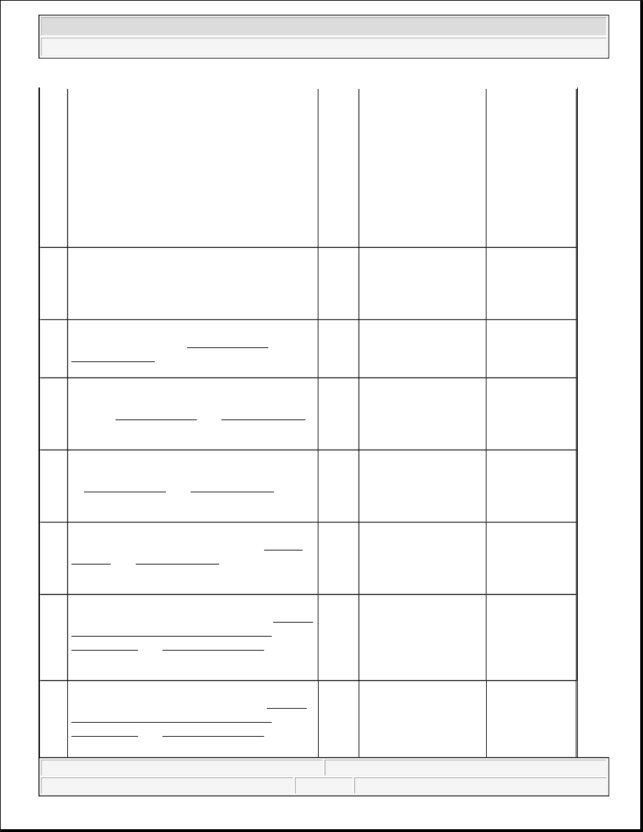
1. Turn OFF the ignition.
2. Disconnect the appropriate mirror.
3. Turn ON the ignition, with the engine
OFF.
4. Measure the voltage between the 5 volt
reference circuit at the mirror harness
connector and a good ground.
Does the voltage measure within the specified
range?
4.75 -
5.25 V
Go to Step 7
Go to Step 10
7
Measure the voltage between the 5 volt
reference circuit and the low reference circuit at
the mirror harness connector.
Does the voltage measure within the specified
range?
4.75 -
5.25 V
Go to Step 12
Go to Step 11
8
Test for a short to voltage on the mirror position
signal circuit. Refer to Circuit Testing and
Wiring Repairs in Wiring Systems.
Did you find and correct the condition?
-
Go to Step 16
Go to Step 13
9
Test the mirror position signal circuit for an
open, high resistance, short to ground or battery.
Refer to Circuit Testing and Wiring Repairs
in Wiring Systems.
Did you find and correct the condition?
-
Go to Step 16
Go to Step 13
10
Test the 5 volt reference circuit for an open,
high resistance, short to ground or battery. Refer
to Circuit Testing and Wiring Repairs in
Wiring Systems.
Did you find and correct the condition?
-
Go to Step 16
Go to Step 13
11
Test the low reference circuit for an open, high
resistance or short to battery. Refer to Circuit
Testing and Wiring Repairs in Wiring
Systems.
Did you find and correct the condition?
-
Go to Step 16
Go to Step 13
12
Inspect for poor connections at the harness
connector of the power mirror. Refer to Testing
for Intermittent Conditions and Poor
Connections and Connector Repairs in Wiring
Systems.
Did you find and correct the condition?
-
Go to Step 16
Go to Step 14
13
Inspect for poor connections at the harness
connector of the DDM/PDM. Refer to Testing
for Intermittent Conditions and Poor
Connections and Connector Repairs in Wiring
Systems.
-
2004 Hummer H2
2004 ACCESSORIES & EQUIPMENT Doors - Hummer H2