Hummer H2. Manual - part 430


  Index      Hummer     Hummer H2 - service repair manual 2004 year


Search            


Content   ..  428  429  430  431   ..


Hummer H2. Manual - part 430


control, memory recall or mirror tilt in reverse functions.

Conditions for Running the DTC 

z

System voltage must be between 9.0-16.0 volts.  

z

The mirror motor control circuits must be active.  

Conditions for Setting the DTC 

z

If the mirror motor control circuits are switched to battery voltage and the mirror motor control circuit is 
shorted to ground.  

z

If the mirror motor control circuits are switched to ground and the mirror motor control circuit is shorted 
to battery voltage.  

Action Taken When the DTC Sets 

The outside rearview mirror will not operate properly on all axes. 

Conditions for Clearing the DTC 

When the fault is no longer present, the door module changes the current DTC to a history DTC. The door 
module will clear the history DTC after 50 fault free ignition cycles, or in response to a scan tool command. 

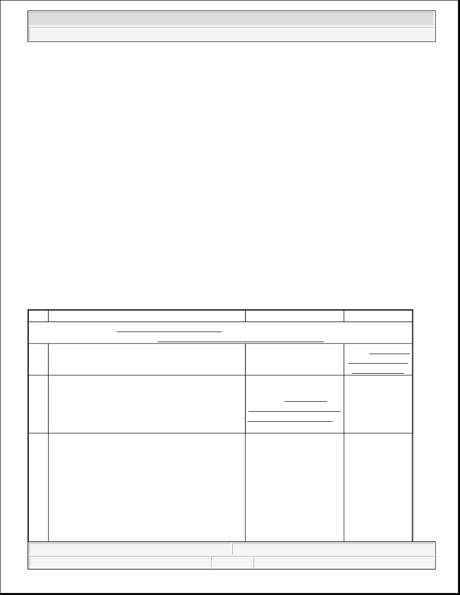
DTC B1544, B1600, or B1605 

Step

Action

Yes

No

Schematic Reference: Outside Mirror Schematics 
Connector End View Reference: Power Door Systems Connector End Views

1

Did you perform the Door Systems Diagnostic 
System Check?

Go to Step 2

Go to Diagnostic 

System Check - 

Door Systems

2

1. Turn ON the ignition, with the engine OFF.  

2. Activate the mirror switch in the up, down left 

and right positions.  

Does the mirror move properly with each activation?

Go to Testing for 

Intermittent Conditions 

and Poor Connections in 

Wiring Systems

Go to Step 3

3

1. Turn OFF the ignition.  

2. Disconnect the mirror from the appropriate 

door module.  

3. Turn ON the ignition, with the engine OFF.  

4. Probe each of the mirror motor down, right and 

up/left control circuit pins at the door module 
one at a time with a test lamp that is connected 
to a good ground.  


2004 Hummer H2 

2004 ACCESSORIES & EQUIPMENT Doors - Hummer H2


DTC B1580, B1590, B1610, OR B1620 

Did the test lamp illuminate at any of the test points?

Go to Step 7

Go to Step 4

4

1. Connect a test lamp between the mirror motor 

down control circuit pin and a good ground.  

2. Activate the mirror switch to the down 

position.  

Does the test lamp illuminate?

Go to Step 5

Go to Step 8

5

1. Connect a test lamp between the mirror motor 

right control circuit pin and a good ground.  

2. Activate the mirror switch to the right position. 

Does the test lamp illuminate?

Go to Step 6

Go to Step 8

6

1. Connect a test lamp between the mirror motor 

up/left control circuit pin and a good ground.  

2. Activate the mirror switch to the up and left 

positions.  

Does the test lamp illuminate?

Go to Step 7

Go to Step 8

7

Inspect for poor connection at the harness connector 
of the appropriate door module. Refer to Testing for 
Intermittent Conditions and Poor Connections
 in 
Wiring Systems. 
Did you find and correct the conditions?

Go to Step 10

Go to Step 9

8

Replace the appropriate door module. Refer to 
Switch Replacement - Door Lock and Side 
Window - Driver
 or Switch Replacement - Door 
Lock and Side Window - Passenger
 .Did you 
complete the replacement?

IMPORTANT:

perform the set up procedure for the appropriate 
door module. Refer to Service Programming 
System (SPS) in Programming.

Go to Step 10

-

9

Replace the mirror. Refer to Mirror Replacement .
Did you complete the replacement?

Go to Step 10

-

10

1. Use the scan tool in order to clear the DTCs.  

2. Operate the vehicle within the Conditions for 

Running the DTC as specified in the 
supporting text.  

Does the DTC reset?

Go to Step 2

System OK


2004 Hummer H2 

2004 ACCESSORIES & EQUIPMENT Doors - Hummer H2


Circuit Description 

The mirror horizontal and vertical position sensors are potentiometers. The Driver Door Module (DDM) and 
Passenger Door Module (PDM) provide these sensors with a 5 volt reference circuit and a low reference circuit. 
The DDM/PDM monitors the horizontal and vertical position sensor signal circuits which change values based 
on mirror position. These voltage values are used to determine mirror position and can be set into memory. 
When the DDM/PDM receives a memory recall request, the DDM/PDM will control the power mirror to the 
memory position based on the horizontal and vertical position sensor signal values. 

Conditions for Running the DTC 

Battery voltage must between 9.0-16.0 volts. 

Conditions for Setting the DTC 

The horizontal and/or vertical position sensor signal(s) are greater than 4.75 volts or less than 0.50 volts. 

Action Taken When the DTC Sets 

Memory movements on the malfunctioning axis are disabled. 

Conditions for Clearing the DTC 

When the fault is no longer present, the DDM/PDM changes the current DTC to a history DTC. The 
DDM/PDM will clear the history DTC after 50 fault free ignition cycles. 

Diagnostic Aids 

z

If DTC B1580 is set by itself, the left horizontal position sensor signal circuit maybe open, shorted to 
ground or battery  

z

If DTC B1590 is set by itself, the left vertical position sensor signal circuit maybe open, shorted to 
ground or battery  

z

If DTC B1610 is set by itself, the right horizontal position sensor signal circuit maybe open, shorted to 
ground or battery  

z

If DTC B1620 is set by itself, the right vertical position sensor signal circuit maybe open, shorted to 
ground or battery.  

z

If DTCs B1580 and B1590 are both set, the left 5 volt reference or low reference circuit(s) maybe open, 
shorted to ground or battery.  

z

If DTCs B1610 and B1620 are both set, the right 5 volt reference or low reference circuit(s) maybe open, 
shorted to ground or battery.  

DTC B1580, B1590, B1610, or B1620 

Step

Action

Value

(s)

Yes

No

Schematic Reference: Outside Mirror Schematics 
Connector End View Reference:Power Door Systems Connector End Views


2004 Hummer H2 

2004 ACCESSORIES & EQUIPMENT Doors - Hummer H2


1

Did you perform the Door Systems Diagnostic 
System Check?

-

Go to Step 2

Go to 

Diagnostic 

System Check -

Door Systems

2

1. Install a scan tool.  

2. Turn ON the ignition, with the engine 

OFF.  

3. With the scan tool, observe the mirror 

horizontal and vertical position 
parameters in the Driver Door Module 
(DDM) and Passenger Door Module 
(PDM) data lists.  

4. Operate both the left and right mirrors 

through the full range of movements.  

Does the scan tool indicate that the left and right 
mirror horizontal and vertical position 
parameters are within the specified range?

0.50-

4.75 V

Go to Testing for 

Intermittent 

Conditions and Poor 

Connections in Wiring 

Systems

Go to Step 3

3

Is there a horizontal and vertical DTC set on the 
same mirror?

-

Go to Step 6

Go to Step 4

4

1. Turn OFF the ignition.  

2. Disconnect the appropriate mirror.  

3. Turn ON the ignition, with the engine 

OFF.  

4. With a scan tool, observe the appropriate 

mirror position parameter.  

Does the scan tool indicate that the mirror 
position parameter is less than the specified 
value?

0.50 V

Go to Step 5

Go to Step 8

5

1. Turn OFF the ignition.  

2. Connect a 3 amp fused jumper wire 

between the 5 volt reference circuit and 
the mirror position signal circuit of the 
appropriate mirror position sensor at the 
mirror harness connector.  

3. Turn ON the ignition, with the engine 

OFF.  

4. With a scan tool, observe the mirror 

position parameter.  

Does the scan tool indicate that the mirror 
position parameter is within the specified range?

4.75 - 

5.25 V

Go to Step 12

Go to Step 9


2004 Hummer H2 

2004 ACCESSORIES & EQUIPMENT Doors - Hummer H2


Content   ..  428  429  430  431   ..