Hummer H2. Manual - part 370


  Index      Hummer     Hummer H2 - service repair manual 2004 year


Search            


Content   ..  368  369  370  371   ..


Hummer H2. Manual - part 370


DTC P0608 

Circuit Description 

The powertrain control module (PCM) creates the vehicle speed output signal by pulsing the circuit to ground. 
The PCM monitors the voltage on the vehicle speed output circuit. If the PCM determines that the voltage is out 
of the normal operating range, a DTC sets. 

Conditions for Running the DTC 

z

The engine speed is more than 400 RPM.  

z

The ignition voltage is between 6.0-18.0 volts.  

Conditions for Setting the DTC 

6

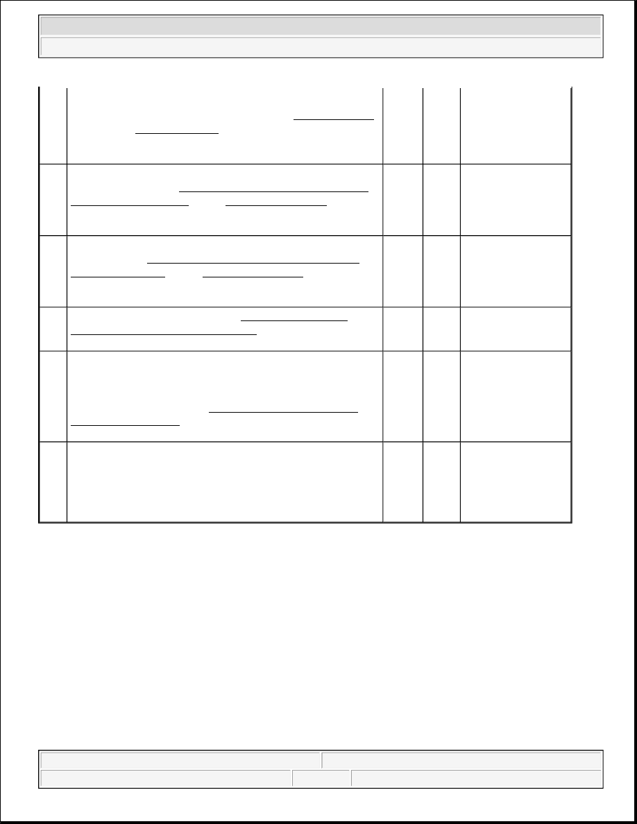
2. Test the low reference circuit of the EOP sensor for an 

open or for a high resistance. Refer to Circuit Testing 
and to Wiring Repairs in Wiring Systems.  

Did you find and correct the condition?

-

Go to 

Step 

11

Go to Step 8

7

Inspect for poor connections at the harness connector of the 
EOP sensor. Refer to Testing for Intermittent Conditions 
and Poor Connections
 and to Connector Repairs in Wiring 
Systems. 
Did you find and correct the condition?

-

Go to 

Step 

11

Go to Step 9

8

Inspect for poor connections at the harness connector of the 
PCM. Refer to Testing for Intermittent Conditions and 
Poor Connections
 and to Connector Repairs in Wiring 
Systems. 
Did you find and correct the condition?

-

Go to 

Step 

11

Go to Step 10

9

Replace the EOP sensor. Refer to Engine Oil Pressure 
Sensor and/or Switch Replacement
 in Engine Mechanical. 
Did you complete the replacement?

-

Go to 

Step 

11

-

10

Replace the PCM. Refer to Powertrain Control Module 
(PCM) Replacement
 in Engine Controls-6.0L (LQ4).Did 
you complete the replacement?

IMPORTANT:

Program the replacement PCM.

-

Go to 

Step 

11

-

11

1. Use the scan tool in order to clear the DTCs.  

2. Operate the vehicle within the Conditions for Running 

the DTC.  

Does the DTC reset?

-

Go to 

Step 2

System OK


2004 Hummer H2 

2004 ACCESSORIES & EQUIPMENT Instrument Panel, Gauges, and Console - Hummer H2


z

The PCM detects that the commanded state of the driver and the actual state of the signal circuit do not 
match.  

z

The above condition must be present for a minimum of 5 seconds.  

Action Taken When the DTC Sets 

The PCM records the operating conditions at the time the diagnostic fails. The PCM displays the failure 
information in the Failure Records on the scan tool. 

Conditions for Clearing the MIL/DTC 

z

The history DTC clears after 40 malfunction free warm-up cycles.  

z

The DTC becomes history when the conditions for setting the DTC are no longer present.  

z

The PCM receives the clear code command from the scan tool.  

DTC P0608 

Step

Action

Value

(s)

Yes

No

Schematic Reference:Instrument Cluster Schematics

1

Did you perform the instrument panel cluster 
(IPC) Diagnostic System Check?

-

Go to Step 2

Go to Diagnostic 

System Check - 

Instrument 

Cluster

2

1. Install a scan tool.  

2. Raise the vehicles drive wheels. Refer 

to Lifting and Jacking the Vehicle in 
General Information.  

3. Start the engine.  

4. Place the transmission into drive for an 

automatic transmission or third gear for 
a manual transmission.  

5. With the scan tool, observe the Vehicle 

Speed Sensor parameter in the 
powertrain control module (PCM) 
Engine Data 1 data list.  

Does the Vehicle Speed Sensor parameter 
match the speedometer display?

-

Go to Testing for 

Intermittent 

Conditions and Poor 

Connections in Wiring 

Systems

Go to Step 3

3

1. Turn OFF the ignition.  

2. Disconnect the PCM connector C2.  

3. Turn ON the ignition, with the engine 

OFF.  

4. Measure the voltage from the vehicle 

9.5 V


2004 Hummer H2 

2004 ACCESSORIES & EQUIPMENT Instrument Panel, Gauges, and Console - Hummer H2


DTC P0654 

speed signal circuit of the PCM to a 
good ground.  

Does the voltage measure greater than the 
specified value?

Go to Step 4

Go to Step 5

4

Test the vehicle speed signal circuit for a 
short to battery voltage. Refer to Circuit 
Testing
 and to Wiring Repairs in Wiring 
Systems. 
Did you find and correct the condition?

-

Go to Step 10

Go to Step 6

5

Test the vehicle speed signal circuit for an 
open, for a short to voltage, or for a short to 
ground. Refer to Circuit Testing and to 
Wiring Repairs in Wiring Systems. 
Did you find and correct the condition?

-

Go to Step 10

Go to Step 7

6

Inspect for poor connections at harness 
connector of the PCM. Refer to Testing for 
Intermittent Conditions and Poor 
Connections
 and to Connector Repairs in 
Wiring Systems. 
Did you find and correct the condition?

-

Go to Step 10

Go to Step 8

7

Inspect for poor connections at the harness 
connector of the IPC. Refer to Testing for 
Intermittent Conditions and Poor 
Connections
 and to Connector Repairs in 
Wiring Systems. 
Did you find and correct the condition?

-

Go to Step 10

Go to Step 9

8

Replace the PCM. Refer to Powertrain 
Control Module (PCM) Replacement
 in 
Engine Controls-6.0L (LQ4).Did you 
complete the replacement?

IMPORTANT:

Program the replacement PCM.

-

Go to Step 10

-

9

Replace the IPC. Refer to Instrument Panel 
Cluster (IPC) Replacement
 . 
Did you complete the replacement?

-

Go to Step 10

-

10

1. Use the scan tool in order to clear the 

DTCs.  

2. Operate vehicle within the Conditions 

for Running this DTC.  

Does the DTC reset?

-

Go to Step 2

System OK


2004 Hummer H2 

2004 ACCESSORIES & EQUIPMENT Instrument Panel, Gauges, and Console - Hummer H2


Circuit Description 

The powertrain control module (PCM) creates the engine speed signal by pulsing the circuit to ground. The 
PCM monitors the voltage on the engine speed signal circuit. If the PCM determines that the voltage is not 
within the normal operating range, the PCM sets a DTC. 

Conditions for Running the DTC 

z

The engine speed is greater than 400 RPM.  

z

The ignition voltage is greater than 6 volts, but less than 18 volts.  

Conditions for Setting the DTC 

z

The PCM detects that the commanded state of the driver and the actual state of the signal circuit do not 
match.  

z

The above condition exists for a minimum of 5.0 seconds.  

Action Taken When the DTC Sets 

z

The PCM stores the DTC information in memory when the diagnostic test runs and fails.  

z

The malfunction indicator lamp (MIL) will not illuminate.  

z

The PCM records the operating conditions at the time when the diagnostic test fails. The PCM stores this 
information in the Failure Records.  

Conditions for Clearing the MIL/DTC 

z

The DTC becomes history when the conditions for setting the DTC are no longer present.  

z

A history DTC is cleared after 40 consecutive malfunction free warm-up cycles.  

z

The PCM receives the clear code command from the scan tool.  

DTC P0654 

Step

Action

Yes

No

Schematic Reference:Instrument Cluster Schematics

1

Did you perform the instrument panel cluster 
(IPC) Diagnostic System Check?

Go to Step 2

Go to Diagnostic 

System Check - 

Instrument 

Cluster

2

1. Install a scan tool.  

2. Start the engine.  

3. With the scan tool, observe the Engine 

Speed parameter in the powertrain control 
module (PCM) Engine Data 1 data list.  

Does the Engine Speed parameter match the 

Go to Testing for 

Intermittent Conditions 

and Poor Connections in 


2004 Hummer H2 

2004 ACCESSORIES & EQUIPMENT Instrument Panel, Gauges, and Console - Hummer H2


Content   ..  368  369  370  371   ..