Hummer H2. Manual - part 367


  Index      Hummer     Hummer H2 - service repair manual 2004 year


Search            


Content   ..  365  366  367  368   ..


Hummer H2. Manual - part 367


DTC P0461 

Circuit Description 

3

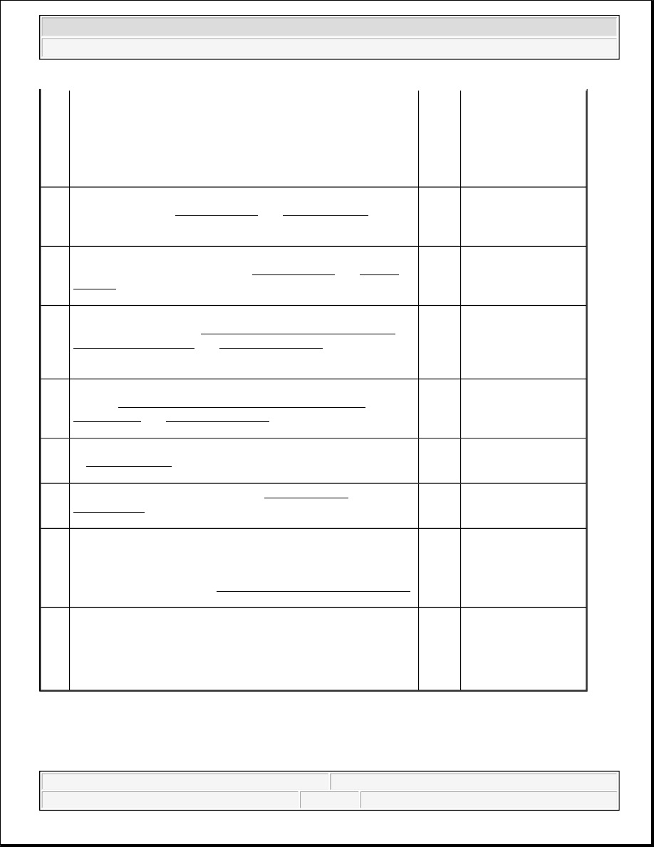
2. Observe the Battery Voltage parameter in the BCM Data 

list.  

3. Turn the ignition OFF.  

Does the Battery Voltage parameter display Active with the 
ignition off?

Go to 

Step 8

Go to Step 7

4

Test the key in ignition signal circuit for an open or a high 
resistance. Refer to Circuit Testing and Wiring Repairs in 
Wiring Systems. 
Did you find and correct the condition?

Go to 

Step 

11

Go to Step 5

5

Test the ground circuit of the ignition key alarm switch for an 
open or a high resistance. Refer to Circuit Testing and Wiring 
Repairs
 in Wiring Systems. 
Did you find and correct the condition?

Go to 

Step 

11

Go to Step 6

6

Inspect for poor connections at the harness connector of the 
ignition switch. Refer to Testing for Intermittent Conditions 
and Poor Connections
 and Connector Repairs in Wiring 
Systems. 
Did you find and correct the condition?

Go to 

Step 

11

Go to Step 9

7

Inspect for poor connections at the harness connector of the BCM. 
Refer to Testing for Intermittent Conditions and Poor 
Connections
 and Connector Repairs in Wiring Systems. 
Did you find and correct the condition?

Go to 

Step 

11

Go to Step 10

8

Repair the short to voltage in the ignition 1 voltage circuit. Refer 
to Wiring Repairs in Wiring Systems. 
Did you correct the condition?

Go to 

Step 

11

-

9

Replace the ignition switch. Refer to Ignition Switch 
Replacement
 in Steering Wheel and Column. 
Did you complete the replacement?

Go to 

Step 

11

-

10

Replace the BCM. Refer to Body Control Module Replacement 
in Body Control System.Did you complete the replacement?

IMPORTANT:

Perform the set up procedure for the replacement BCM.

Go to 

Step 

11

-

11

1. Use the scan tool in order to clear the DTCs.  

2. Operate the vehicle within the Conditions for Running the 

DTC as specified in the supporting text.  

Does the DTC reset?

Go to 

Step 2

System OK


2004 Hummer H2 

2004 ACCESSORIES & EQUIPMENT Instrument Panel, Gauges, and Console - Hummer H2


The fuel level sensor changes resistance in response to the fuel level. The powertrain control module (PCM) 
monitors the signal circuit of the fuel level sensor in order to determine the fuel level. When the fuel tank is full, 
the sensor resistance is low and the PCM senses a low signal voltage. When the fuel tank is empty, the sensor 
resistance is high and the PCM senses a high signal voltage. The PCM uses the signal circuit of the fuel level 
sensor in order to calculate the percentage of remaining fuel in the tank. The PCM sends the fuel level 
percentage via the class 2 serial data circuit to the instrument cluster in order to control the fuel gauge. The fuel 
level information is also used for misfire and evaporative emission (EVAP) diagnostics. 

This diagnostic tests for a stuck fuel level sensor signal. The PCM sets this DTC if the fuel level sensor signal 
appears to be stuck based on a lack of signal variation expected during normal operation. 

Conditions for Running the DTC 

The engine is running. 

Conditions for Setting the DTC 

The PCM does not detect a change in fuel level of at least 3.0L (0.79 gal) over a distance of 320 km (200 
miles). 

Action Taken When the DTC Sets 

z

The fuel gauge defaults to empty.  

z

The low fuel indicator illuminates.  

z

The PCM records the operating conditions at the time that the diagnostic test fails. The PCM displays the 
failure information in the Failure Records on the scan tool.  

Conditions for Clearing the DTC 

z

The DTC becomes history when the conditions for setting the DTC are no longer present.  

z

The history DTC clears after 40 malfunction free warm-up cycles.  

z

The PCM receives the clear code command from the scan tool.  

Diagnostic Aids 

z

Use the Freeze Frame/Failure Records data in order to locate an intermittent condition. If you cannot 
duplicate the DTC, the information included in the Freeze Frame/Failure Records data may help in 
determining the number of miles since the DTC set. The Fail Counter and Pass Counter can also help in 
determining the number of ignition cycles that the diagnostic test reported a pass and/or fail. Operate the 
vehicle within the same freeze frame conditions, including those for RPM, for engine load, for vehicle 
speed, for temperature, and for others. This will isolate at what point the DTC failed.  

z

Refer to Testing for Intermittent Conditions and Poor Connections in Wiring Systems.  

DTC P0461 

Step

Action

Yes

No

Schematic Reference:Instrument Cluster Schematics


2004 Hummer H2 

2004 ACCESSORIES & EQUIPMENT Instrument Panel, Gauges, and Console - Hummer H2


DTC P0462 

Circuit Description 

The fuel level sensor changes resistance in response to fuel level. The PCM monitors the signal circuit of the 
fuel level sensor in order to determine the fuel level. When the fuel tank is full, the sensor resistance is low and 
the PCM senses a low signal voltage. When the fuel tank is empty, the sensor resistance is high and the PCM 
senses a high signal voltage. The PCM uses the signal circuit of the fuel level sensor in order to calculate the 
percentage of remaining fuel in the tank. The PCM sends the fuel level percentage via the class 2 serial data 
circuit to the instrument cluster in order to control the fuel gauge. The fuel level information is also used for 
misfire and EVAP diagnostics. 

Conditions for Running the DTC 

The engine is running. 

Conditions for Setting the DTC 

z

The sender output is less than 0.39 volts.  

z

The above condition is present for greater than 30 seconds.  

Action Taken When the DTC Sets 

z

The fuel gauge defaults to empty.  

z

The low fuel indicator illuminates.  

1

Did you perform the Diagnostic System Check - 
Instrument Cluster?

Go to 

Step 2

Go to Diagnostic System 

Check - Instrument Cluster

2

1. Remove the fuel level sender.  

2. Inspect for the following items: 

z

The fuel level sensor is stuck, perhaps due to 
an interference with the fuel strainer.  

z

The fuel tank contains foreign material, for 
instance, ice.  

Did you find and correct the condition?

Go to 

Step 4

Go to Step 3

3

Replace the fuel level sensor. Refer to Fuel Level Sensor 
Replacement
 in Engine Controls - 6.0L (LQ4). 
Did you complete the replacement?

Go to 

Step 4

-

4

1. Use the scan tool in order to clear the DTCs.  

2. Operate the vehicle within the Conditions for 

Running the DTC as specified in the supporting text. 

Does the DTC reset?

Go to 

Step 2

System OK


2004 Hummer H2 

2004 ACCESSORIES & EQUIPMENT Instrument Panel, Gauges, and Console - Hummer H2


z

The PCM records the operating conditions at the time that the diagnostic test fails. The PCM displays the 
failure information in the Failure Records on the scan tool.  

Conditions for Clearing the DTC 

z

The DTC becomes history when the conditions for setting the DTC are no longer present.  

z

The history DTC clears after 40 malfunction free warm-up cycles.  

z

The PCM receives the clear code command from the scan tool.  

Diagnostic Aids 

z

Use the Freeze Frame/Failure Records data in order to locate an intermittent condition. If you cannot 
duplicate the DTC, the information included in the Freeze Frame/Failure Records data may help in 
determining the number of miles since the DTC set. The Fail Counter and Pass Counter can also help in 
determining the number of ignition cycles that the diagnostic test reported a pass and/or fail. Operate the 
vehicle within the same freeze frame conditions, including those for RPM, for engine load, for vehicle 
speed, for temperature, and for others. This will isolate at what point the DTC failed.  

z

Refer to Testing for Intermittent Conditions and Poor Connections in Wiring Systems.  

Test Description 

The number below refers to the step number on the diagnostic table. 

3: Tests for the proper operation of the circuit in the high voltage range.  

DTC P0462 

Step

Action

Value

(s)

Yes

No

Schematic Reference: Instrument Cluster Schematics

1

Did you perform the Instrument Cluster Diagnostic System 
Check?

-

Go to 

Step 2

Go to Diagnostic 

System Check - 

Instrument Cluster

2

1. Install a scan tool.  

2. Turn the ignition ON, with the engine OFF.  

3. With a scan tool, observe the Fuel Tank Level 

Remaining parameter in the PCM Enhanced EVAP 
data list.  

Does the scan tool indicate that the Fuel Tank Level 
Remaining parameter is greater than the specified value?

98%

Go to 

Step 3 Go to Diagnostic Aids

1. Turn the ignition OFF.  

2. Disconnect C106.  

3. Turn the ignition ON, with the engine OFF.  


2004 Hummer H2 

2004 ACCESSORIES & EQUIPMENT Instrument Panel, Gauges, and Console - Hummer H2


Content   ..  365  366  367  368   ..