Hummer H2. Manual - part 311
The park lamps will not operate or will remain always on.
Conditions for Clearing the MIL/DTC
z
This DTC will clear on current status after the condition for setting the fault is corrected.
z
A history DTC will clear after 100 consecutive ignition cycles without a fault present.
z
History and current DTC(s) can be cleared using a scan tool.
Test Description
The numbers below refer to the step numbers on the diagnostic table.
2: Listen for an audible click when the park lamp relay operates. Command both the ON and OFF states.
Repeat the commands as necessary.
3: Tests for voltage at the coil side of the park lamp relay.
4: Verifies that the body control module (BCM) is providing ground to the park lamp relay.
5: Tests if ground is constantly being applied to the park lamp relay.
6: Tests if there is opposing voltage present or an open park lamp relay control circuit.
12: After replacement of the BCM you must calibrate the new module for proper operation.
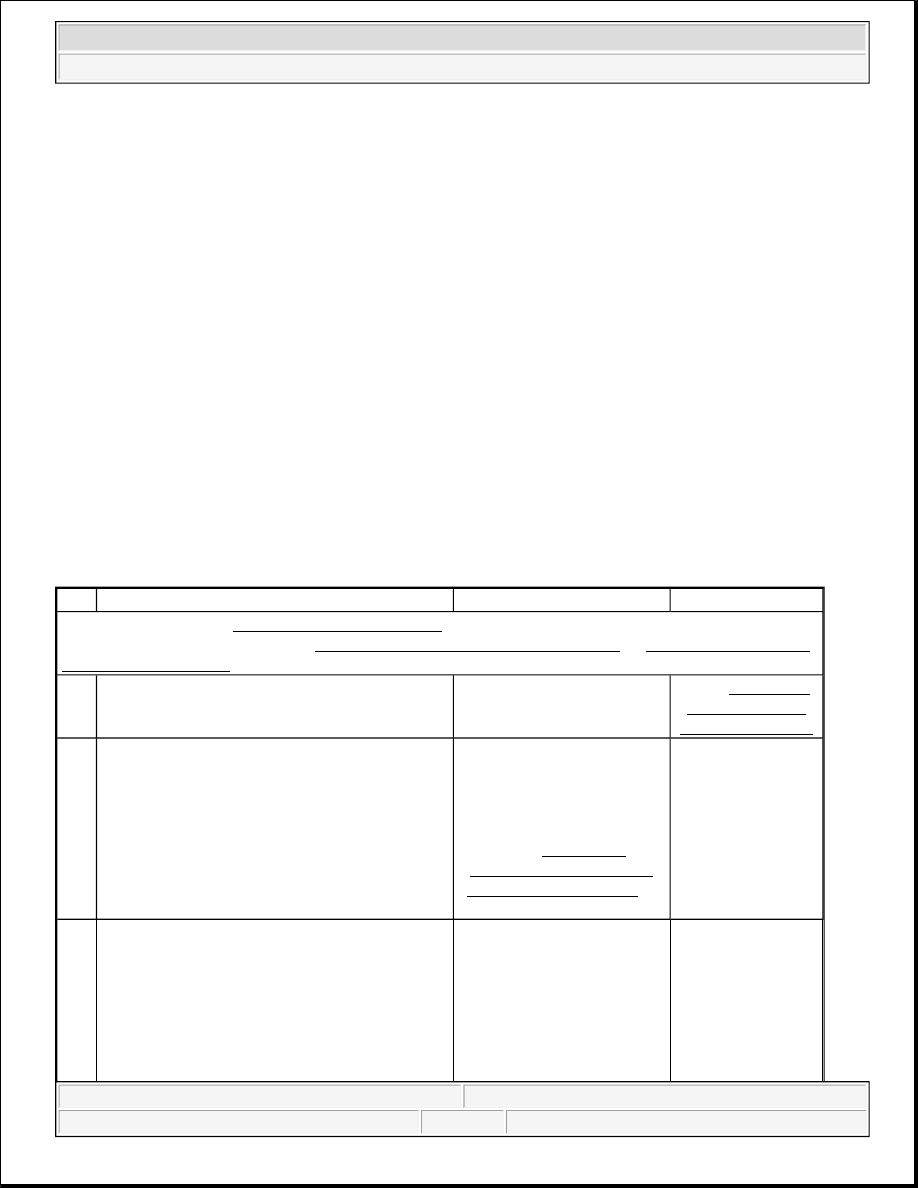
DTC B2585
Step
Action
Yes
No
Schematic Reference: Exterior Lights Schematics
Connector End View Reference: Lighting Systems Connector End Views or Body Control System
Connector End Views in Body Control System
1
Did you perform the Lighting Systems
Diagnostic System Check?
Go to Step 2
Go to Diagnostic
System Check -
Lighting Systems
2
1. Install a scan tool.
2. Turn ON the ignition, with the engine
OFF.
3. With a scan tool, command the park lamp
relay ON and OFF.
Does the park lamp relay turn ON and OFF with
each command?
Go to Testing for
Intermittent Conditions
and Poor Connections in
Wiring Systems
Go to Step 3
3
1. Turn OFF the ignition.
2. Disconnect the park lamp relay.
3. Turn ON the ignition, with the engine
OFF.
4. Connect a test light between the battery
positive voltage circuit of the parklamp
2004 Hummer H2
2004 ACCESSORIES & EQUIPMENT Lighting Systems - Hummer H2