Hummer H2. Manual - part 2652


  Index      Hummer     Hummer H2 - service repair manual 2004 year


Search            


Content   ..  2650  2651  2652  2653   ..


Hummer H2. Manual - part 2652


commands the neutral indicator light On.

Rear Axle Lock  

The scan tool displays On or Off. This parameter indicates On when the transfer case shift control module 
commands the rear axle lock solenoid to be applied. 

Rear Axle Lock Indicator Light  

The scan tool displays On or Off. On is displayed when the transfer case shift control module requests the 
rear axle lock indicator On. 

Rear Axle Lock Request  

The scan tool displays On or Off. On is displayed when the transfer case shift control module receives a 
rear axle lock request from the switch or a scan tool. 

Software ID  

The scan tool displays a numeric value. This parameter indicates which version of software is currently 
installed in the transfer case shift control module. 

DIAGNOSTIC TROUBLE CODE (DTC) LIST 

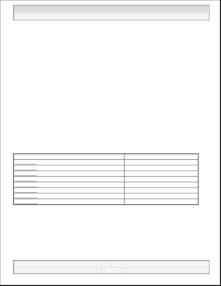
Diagnostic Trouble Code (DTC) List 

DTC B0790 

Circuit Description 

The neutral indicator circuit consists of a ignition 3 voltage circuit and a neutral indicator control circuit. When 
the neutral mode has been selected by the driver, current is supplied to the neutral indicator by the ignition 3 
voltage circuit, traveling through the neutral indicator LED at which time the transfer case shift control module 
supplies the ground through the neutral indicator control circuit. This DTC indicates an open, short to ground or 
a short to voltage. 

Description

Module

DTC B0790

FT4WD

DTC B2725

FT4WD

DTC C0306

FT4WD

DTC C0327

FT4WD

DTC C0329

FT4WD

DTC C0359

FT4WD

DTC C0388

FT4WD

DTC C0550

FT4WD


2004 Hummer H2 

2004 DRIVELINE/AXLE Transfer Case - BW 4484 - Hummer H2


Conditions for Running the DTC 

z

The ignition is ON.  

z

The system voltage is 9-18 volts.  

Conditions for Setting the DTC 

z

The system monitors the voltage on the neutral indicator control circuit.  

z

If the system detects a voltage 3.5 volts or less when the neutral indicator is not commanded, the DTC is 
logged.  

z

If the system detects a voltage 3.5 volts or more when the neutral indicator is commanded, the DTC is 
logged.  

Action Taken When the DTC Sets 

The SERVICE 4WD indicator will remain illuminated for the remainder of the current ignition cycle. 

Conditions for Clearing the DTC 

z

The transfer case shift control module will clear the DTC if the condition for setting the DTC is not 
currently present.  

z

A history DTC will clear after 33 consecutive ignition cycles without a fault present.  

z

History DTCs can be cleared using a scan tool.  

Test Description 

The numbers below refer to the step numbers on the diagnostic table. 

2: This step tests for voltage at the ignition 3 voltage side of the transfer case select switch.  

3: This step tests the control circuit of the neutral indicator for a short to voltage or an open.  

4: This step tests the control circuit of the neutral indicator for a short to ground.  

DTC B0790 

Step

Action

Yes

No

Schematic Reference: Transfer Case Control Schematics 
Connector End View Reference: Transfer Case Control Connector End Views

1

Did you perform the Diagnostic System Check-Transfer Case?

Go to 

Step 

2

Go to Diagnostic 

System Check - 

Transfer Case

2

1. Turn the ignition OFF.  

2. Remove the transfer case select switch.  

3. Disconnect the connector on the transfer case select switch.  

4. Turn the ignition ON.  


2004 Hummer H2 

2004 DRIVELINE/AXLE Transfer Case - BW 4484 - Hummer H2


DTC B2725 

Circuit Description 

The mode switch circuit consists of 5 modes. The transfer case shift control module supplies a regulated 5 volts, 
DC to the switch through the 5 volt regulator circuit. The current travels through the resistor of the currently 
pressed mode button. The current is then returned to the transfer case shift control module through the switch 
signal circuit. 

The transfer case shift control module constantly monitors this signal voltage to determine the condition of the 
mode switch circuit. 

When each of the modes are selected they will complete a circuit through their own specific resistor while the 
button is pressed. The transfer case shift control module continuously monitors the switch input to determine 

5. Probe the Ignition 3 voltage circuit with a DMM that is 

connected to a good ground.  

Does the DMM indicate battery voltage?

Go to 

Step 

3

Go to Step 6

3

Test the neutral indicator control circuit for a short to voltage or an 
open. Refer to Circuit Testing and Wiring Repairs in Wiring 
Systems. 
Did you find and correct the condition?

Go to 

Step 

9

Go to Step 4

4

Test the neutral indicator control circuit for a short to ground. Refer to 
Testing for Short to Ground and Wiring Repairs in Wiring Systems.
Did you find and correct the condition?

Go to 

Step 

9

Go to Step 5

5

Inspect for poor connections at the harness connector of the transfer 
case shift control module, and the transfer case shift control switch. 
Refer to Testing for Intermittent Conditions and Poor Connections 
and Connector Repairs in Wiring Systems. 
Did you find and correct the condition?

Go to 

Step 

9

Go to Step 7

6

Repair the ignition 3 voltage circuit of the transfer case select switch 
for an open, high resistance or short to ground. 
Did you complete the repair?

Go to 

Step 

9

-

7

Replace the transfer case select switch, and clear all DTCs. Refer to 
Transfer Case Shift Control Switch Replacement . 
Does the DTC reset?

Go to 

Step 

8

System OK

8

Replace the transfer case shift control module. Refer to Transfer Case 
Shift Control Module Replacement
 . 
Did you complete the repair?

Go to 

Step 

9

-

9

1. Use the scan tool in order to clear the DTCs.  

2. Operate the vehicle within the Conditions for Running the DTC 

as specified in the supporting text.  

Does the DTC reset?

Go to 

Step 

1

System OK


2004 Hummer H2 

2004 DRIVELINE/AXLE Transfer Case - BW 4484 - Hummer H2


whether the Neutral, Differential Lock, 4HI, 4HI Lock, or 4LO Lock mode was selected by the driver.

Conditions for Running the DTC 

z

The ignition is ON.  

z

The system voltage is 9-18 volts.  

Conditions for Setting the DTC 

z

The system constantly monitors the voltage on switch signal circuit.  

z

If the system detects a voltage level under 0.3 volt or greater than 0.75 volts, the DTC is logged.  

Action Taken When the DTC Sets 

z

All shifting will be disabled.  

z

The SERVICE 4WD indicator will remain illuminated for the remainder of the current ignition cycle.  

Conditions for Clearing the DTC 

z

The transfer case shift control module will clear the current DTC if the condition for setting the DTC is 
not currently present.  

z

A history DTC will clear after 33 consecutive ignition cycles without a fault present.  

z

History DTCs can be cleared using a scan tool.  

Test Description 

The numbers below refer to the step numbers on the diagnostic table. 

2: This step tests for proper operation of the transfer case mode select switch.  

3: This step tests the mode switch for proper resistance values in all mode switch states.  

4: This step tests for proper voltage on the 5 volt reference circuit.  

5: This step tests the 5 volt reference circuit for an open, high resistance, short to voltage, or short to 
ground.  

6: This step tests the switch signal circuit for an open, high resistance, short to voltage, or short to ground. 

DTC B2725 

Step

Action

Values

Yes

No

Schematic Reference: Transfer Case Control Schematics 
Connector End View Reference: Transfer Case Control Connector End Views

1

Did you perform the Diagnostic System 
Check-Transfer Case?

-

Go to Step 2

Go to 

Diagnostic 

System Check - 

Transfer Case

1. Install a scan tool.  


2004 Hummer H2 

2004 DRIVELINE/AXLE Transfer Case - BW 4484 - Hummer H2


Content   ..  2650  2651  2652  2653   ..