Hummer H2. Manual - part 260


  Index      Hummer     Hummer H2 - service repair manual 2004 year


Search            


Content   ..  258  259  260  261   ..


Hummer H2. Manual - part 260


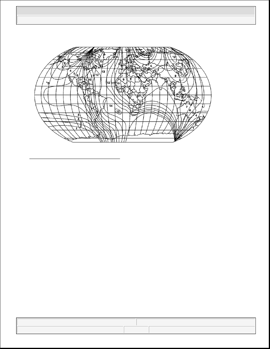
Fig. 45: World Magnetic Variation Map 
Courtesy of GENERAL MOTORS CORP. 

1. Locate your current geographic location on the World Magnetic Variation Map.  

2. Turn ON the ignition, with the engine OFF.  

3. Press and hold the switch for the compass, which may be depicted as COMP, COMPASS, or on/off 

(w/UE1) depending on the type of mirror on the vehicle, until a zone number appears on the compass 
display.  

4. Depress the switch for the compass to select the desired zone number.  

5. Wait 5 seconds. The display will return to a compass heading. The variance procedure is now complete.  

6. Calibrate the compass. Refer to Compass Calibration mentioned above.  

REAR WINDOW DEFOGGER DESCRIPTION AND OPERATION 

Rear Window Defogger System Components 

The rear window defogger system consist of the following components: 

z

HVAC control module  

z

Body control module (BCM)  

z

DEFOG relay  

z

Rear window defogger grid  

Rear Window Defogger Operation 


2004 Hummer H2 

2004 ACCESSORIES & EQUIPMENT Stationary Windows - Hummer H2


Battery positive voltage is supplied through the RR DEFOG fuse, in the underhood fuseblock, to the DEFOG 
relay switched input. When you turn ON the ignition, ignition voltage is supplied through the SEO IGN fuse, in 
the underhood fuseblock, to the DEFOG relay coil. When you depress the rear window defogger switch. The 
HVAC control module illuminates the rear window defogger indicator and sends a class 2 message to the BCM 
to enable the rear window defogger system. The BCM energizes the DEFOG relay by grounding the control 
circuit of the relay. This allows battery positive voltage from the relay switched input through the switch 
contacts and out the relay switched output to the rear window defogger grid. Ground for the rear window 
defogger grid is provided by G301. 

When you turn ON the ignition and press the rear window defogger switch, the defogger cycle lasts 10 minutes. 
Further operation results in additional 10 minute defogger cycles. 

STATIONARY WINDOW DESCRIPTION 

Most stationary windows, specifically windshields, are retained to the body with urethane adhesive which 
adheres the window to the body, increasing structural integrity. The reinstallation of the windows with urethane 
adhesive requires complete replacement of the urethane adhesive bead, and is know as the Full Cut Method. 

FULL-CUT METHOD DESCRIPTION 

Use only the full cut method also know as in the field as Full Strip Method when installing windows. 

This method includes the following: 

z

The replacement of a majority of the urethane adhesive bead remove all but approximately 2 mm (3/64 
in) of the existing bead of urethane adhesive from the pinch-weld flange.  

z

Applying pinch-weld primer to any exposed painted areas on the pinch-weld flange.  

No mounds or loose pieces of urethane adhesive should remain on the pinch-weld flange. Do not remove all 
traces of urethane adhesive. 

IMPORTANT:

z

If corrosion of the pinch-weld flange is present, or if sheet metal repairs or 
replacements are required, refinish the pinch-weld flange in order to 
present a clean, primer-only surface.  

z

If paint repairs are required, mask the flange bonding area, prior to 
applying the color coat, in order to provide a clean, primer-only surface.  

z

Appropriate materials for these primer applications are typically 2 
component catalyzed products. Use materials such as BASF DE15(R), 
DuPont 2610(R), Sherwin-Williams PSE 4600 and NP70(R) and Martin-
Semour 5120,5130(R), PPG DP90LF SPIES/ HECKER 3688/8590 - 
3688/5150 - 4070/5090 STANDOX 11158/13320 - 14653/14980 products are 
approved for this application. Follow the manufacturer's directions for the 
mix, the application, and the drying times.  

z

After repairing the opening as indicated, shake the pinch-weld primer 
black #3 well. Using a new dauber, apply the primer to the primed surface 


2004 Hummer H2 

2004 ACCESSORIES & EQUIPMENT Stationary Windows - Hummer H2


SPECIAL TOOLS AND EQUIPMENT 

SPECIAL TOOLS 

Special Tools 

of the flange in the bonding area. Allow the primer to dry for 10 minutes.  

Illustration

Tool Number/Description

J 24402-A 

Glass Sealant Cold Knife Remover

J 34946 

Window Pin Remover

J 39032 

Stationary Glass Removal Tool

J 39040 

Quarter Window Remover


2004 Hummer H2 

2004 ACCESSORIES & EQUIPMENT Stationary Windows - Hummer H2


2004 ACCESSORIES & EQUIPMENT

Vehicle DTC Information - Hummer H2 

DIAGNOSTIC INFORMATION AND PROCEDURES 

DIAGNOSTIC TROUBLE CODE (DTC) LIST - VEHICLE 

Diagnostic Trouble Code (DTC) List - Vehicle 

DTC

Descriptor

DTC B0001

Vehicle Speed Information Circuit Range/Performance

DTC B0016, B0017, or B0018

Right Front/Passenger Frontal Deployment Loop (Stage 1) 
Circuit

DTC B0022, B0024, or B0026

Left Front/Driver Frontal Deployment Loop (Stage 1) Circuit

DTC B0051

Deployment Commanded

DTC B0053

Deployment Commanded with Loop Malfunctions Present

DTC B0090

Active Switch Voltage Out of Range

DTC B0091

Active Switch Wrong State

DTC B0100, B0101, B0102, B0103, 

B0104, or B0105

Electronic Frontal Sensor Circuit

DTC B0159

Outside Air Temperature Sensor Circuit Range/Performance

DTC B0164

Passenger Compartment Temperature Sensor #1 (Single 
Sensor or LH) Circuit Range/Performance

DTC B0174, B0179, B0510, or B0515

Discharge Air Temperature Sensor Circuit

DTC B0183 or B0188

Sunload Sensor Circuit

DTC B0229, B0414, B0424, or B3770

HVAC Door Actuator Range/Performance

DTC B0263, B0268, B0408, or B0418

HVAC Door Actuator Circuit

DTC B0283

Electric Rear Defrost Circuit

DTC B0540

Speedometer Circuit

DTC B0560

Tachometer Circuit Range/Performance

DTC B0790

Transfer Case Neutral Indicator Circuit

DTC B1000

ECU Malfunction

DTC B1001

Option Configuration Error

DTC B1004

Keep Alive Memory (KAM) Reset

DTC B1007

EEPROM Write Error

DTC B1009

EEPROM Checksum Mismatch

DTC B1023

Integral Switch Performance

DTC B1025, B1035, B1045, or B1055

Audio [+] Output Circuit

DTC B1235

Amplifier On Signal Circuit

DTC B1271

Theft Locked

DTC B1372

Device Ignition 1 (ON and START) Circuit Low

DTC B1375

Device Ignition 3 (ON) Circuit


2004 Hummer H2 

2004 ACCESSORIES & EQUIPMENT Vehicle DTC Information - Hummer H2


2004 Hummer H2 

2004 ACCESSORIES & EQUIPMENT Vehicle DTC Information - Hummer H2


Content   ..  258  259  260  261   ..