Hummer H2. Manual - part 1874


  Index      Hummer     Hummer H2 - service repair manual 2004 year


Search            


Content   ..  1872  1873  1874  1875   ..


Hummer H2. Manual - part 1874


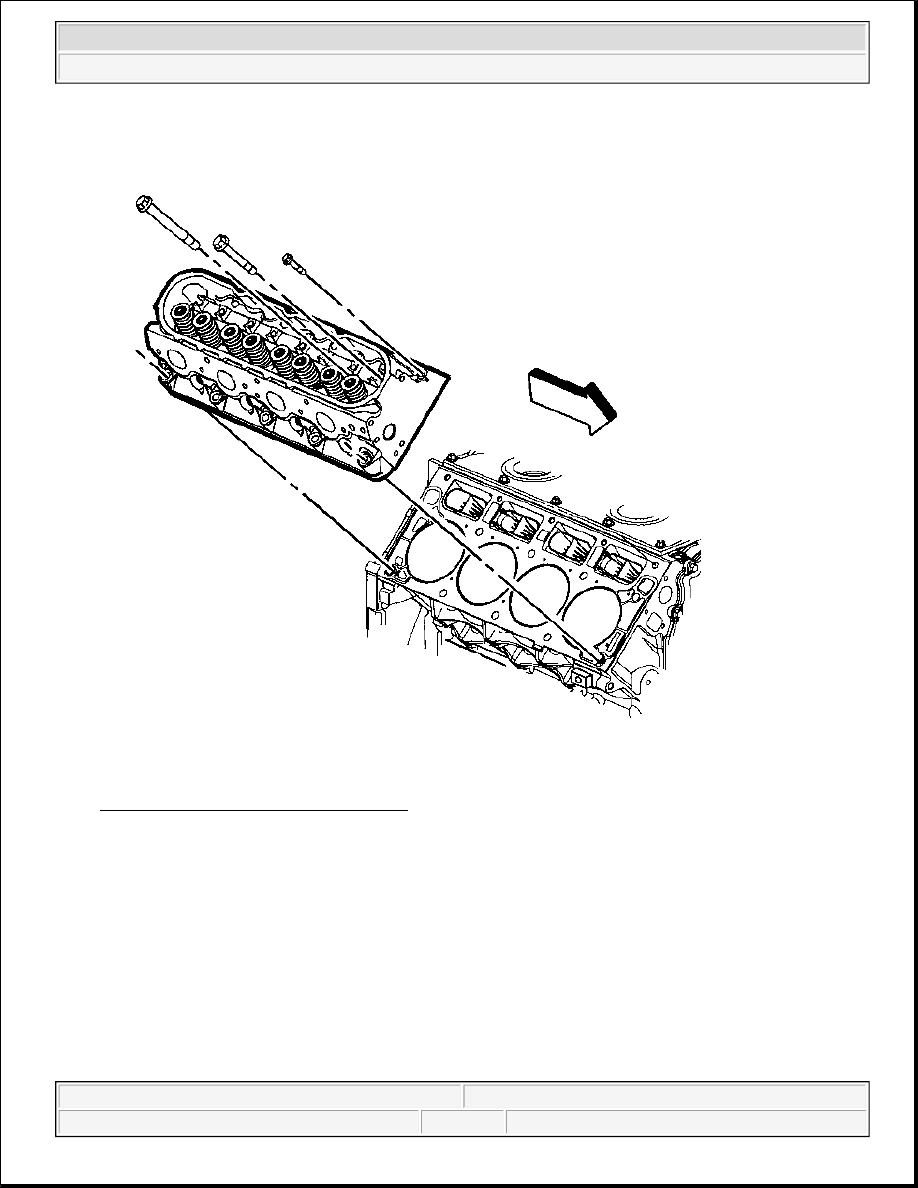
Fig. 650: Cylinder Head & Bolts (Right) 
Courtesy of GENERAL MOTORS CORP. 

8. Install the cylinder head onto the locating pins and the gasket.  

9. Install the NEW cylinder head bolts. 


2004 Hummer H2 

2004 ENGINE Engine Mechanical - 4.8L, 5.3L, and 6.0L - Hummer H2


Fig. 651: Cylinder Head Bolt Tightening Sequence (Right) 
Courtesy of GENERAL MOTORS CORP. 

10. Tighten the first design cylinder head bolts. 

Tighten:  

1. Tighten the first design M11 cylinder head bolts a first pass in sequence to 30 N.m (22 lb ft).  

2. Tighten the first design M11 cylinder head bolts a second pass in sequence to 90 degrees using the 

J 45059 . See Special Tools and Equipment .  

3. Tighten the first design M11 cylinder head bolts (1,2,3,4,5,6,7,8) to 90 degrees and the M11 

cylinder head bolts (9 and 10) to 50 degrees a final pass in sequence to using the J 45059 . See 
Special Tools and Equipment .  

4. Tighten the M8 cylinder head bolts (11,12,13,14,15) to 30 N.m (22 lb ft). Begin with the center bolt 

(11) and alternating side-to-side, work outward tightening all of the bolts.  

11. Tighten the second design cylinder head bolts. 

Tighten:  

1. Tighten the second design M11 cylinder head bolts (1-10) a first pass in sequence to 30 N.m (22 lb 

ft).  

2. Tighten the second design M11 cylinder head bolts (1-10) a second pass in sequence to 90 degrees 

using the J 45059 . See Special Tools and Equipment .  

3. Tighten the second design M11 cylinder head bolts (1-10) a final pass in sequence to 70 degrees 

using the J 45059 . See Special Tools and Equipment .  

4. Tighten the M8 cylinder head bolts (11,12,13,14,15) to 30 N.m (22 lb ft). Begin with the center bolt 

(11) and alternating side-to-side, work outward tightening all of the bolts.  

NOTE:

Refer to Fastener Notice in Cautions and Notices.


2004 Hummer H2 

2004 ENGINE Engine Mechanical - 4.8L, 5.3L, and 6.0L - Hummer H2


VALVE ROCKER ARM AND PUSH ROD INSTALLATION

Fig. 652: Valve Rocker Arm Pivot Support 
Courtesy of GENERAL MOTORS CORP. 

1. Lubricate the valve rocker arms and pushrods with clean engine oil.  

2. Lubricate the flange of the valve rocker arm bolts with clean engine oil. 

Lubricate the flange or washer surface of the bolt that will contact the valve rocker arm. 

IMPORTANT:

z

When using the valve train components again, always install the 
components to the original location and position.  

z

Valve lash is net build, no valve adjustment is required.  


2004 Hummer H2 

2004 ENGINE Engine Mechanical - 4.8L, 5.3L, and 6.0L - Hummer H2


3. Install the valve rocker arm pivot support. 

Fig. 653: View Of Pushrods 
Courtesy of GENERAL MOTORS CORP. 

4. Install the pushrods. 

IMPORTANT: Ensure that the pushrods seat properly to the valve lifter sockets.


2004 Hummer H2 

2004 ENGINE Engine Mechanical - 4.8L, 5.3L, and 6.0L - Hummer H2


Content   ..  1872  1873  1874  1875   ..