Hummer H2. Manual - part 1263


  Index      Hummer     Hummer H2 - service repair manual 2004 year


Search            


Content   ..  1261  1262  1263  1264   ..


Hummer H2. Manual - part 1263


GENERAL ELECTRICAL DIAGNOSIS PROCEDURES 

Basic Knowledge Required 

Without a basic knowledge of electricity, it will be difficult to use the diagnostic procedures contained in the 
service manual. You should understand the basic theory of electricity, and know the meaning of voltage (volts), 
current (amps), and resistance (ohms). You should also be able to read and understand a wiring diagram, as well 
as understand what happens in a circuit with an open or a shorted wire. 

CHECKING AFTERMARKET ACCESSORIES 

Do not connect aftermarket accessories into the following circuits: 

z

SIR circuits, all such circuits are indicated on circuit diagrams with the SIR symbol. 

z

OBD II circuits, all such circuits are indicated on circuit diagrams with the OBD II symbol.  

Always check for aftermarket accessories (non-OEM) as the first step in diagnosing electrical problems. If the 
vehicle is so equipped, disconnect the system to verify that these add-on accessories are not the cause of the 
problems. 

Possible causes of vehicle problems related to aftermarket accessories include: 

z

Power feeds connected to points other than the battery  

z

Antenna location  

z

Transceiver wiring located too close to vehicle electronic modules or wiring  

z

Poor shielding or poor connectors on antenna feed line  

z

Check for recent service bulletins detailing installation guidelines for aftermarket accessories. 

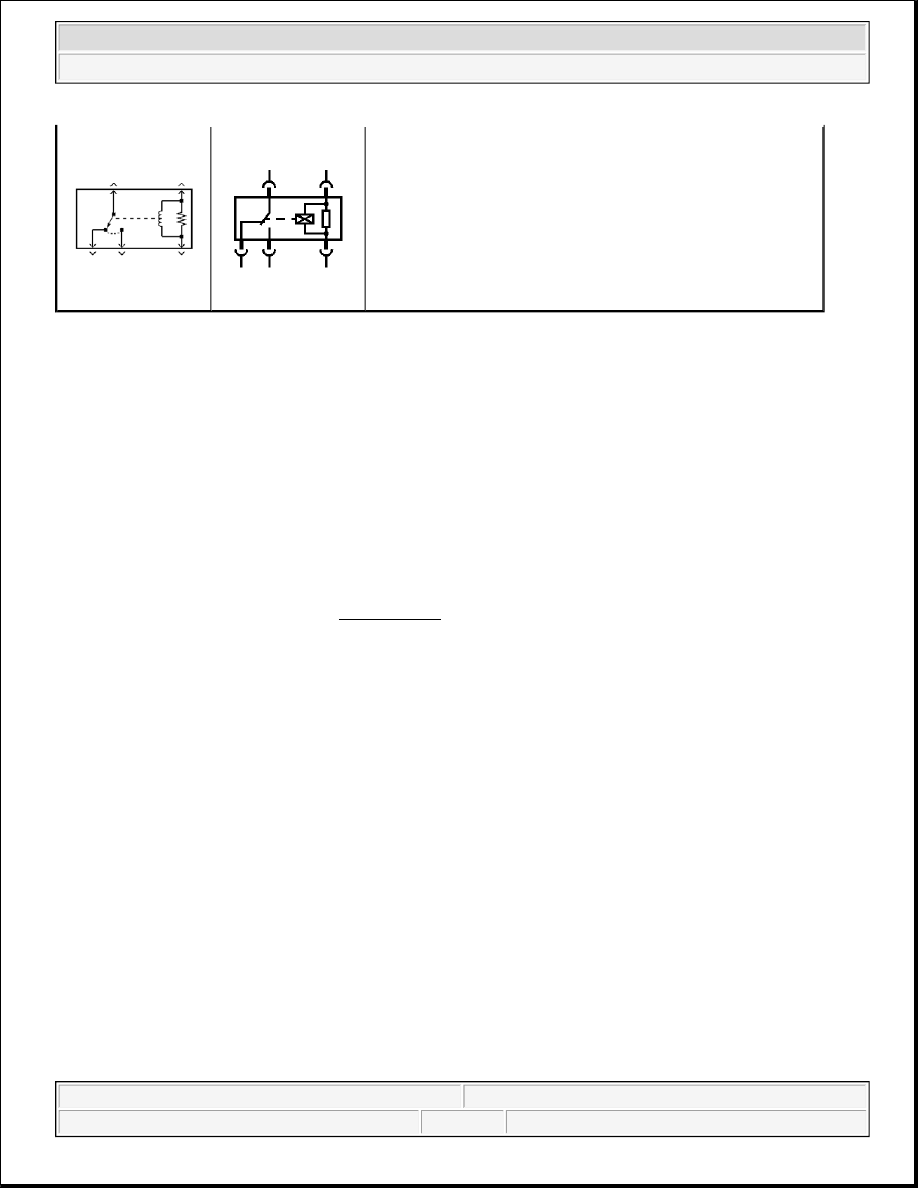
Single Pole/Throw Relay - Normally Closed

CAUTION: Refer to SIR Caution in Cautions and Notices.

NOTE:

Refer to OBD II Symbol Description Notice in Cautions and Notices.


2004 Hummer H2 

2004 ACCESSORIES & EQUIPMENT Wiring Systems - Hummer H2


CIRCUIT TESTING 

The Circuit Testing section contains the following diagnostic testing information. Using this information along 
with the diagnostic procedures will identify the cause of the electrical malfunction. 

z

Using Connector Test Adapters  

z

Probing Electrical Connectors  

z

Troubleshooting with a Digital Multimeter  

z

Troubleshooting with a Test Lamp  

z

Using Fused Jumper Wires  

z

Measuring Voltage  

z

Measuring Voltage Drop  

z

Measuring Frequency  

z

Testing for Continuity  

z

Testing for Short to Ground  

z

Testing for a Short to Voltage  

USING CONNECTOR TEST ADAPTERS 

PROBING ELECTRICAL CONNECTORS 

Frontprobe 

Disconnect the connector and probe the terminals from the mating side (front) of the connector. 

NOTE:

Do not insert test equipment probes (DVOM etc.) into any connector or fuse 
block terminal. The diameter of the test probes will deform most terminals. A 
deformed terminal will cause a poor connection, which will result in a system 
failure. Always use the J-35616 GM-Approved Terminal Test Kit or the J 42675 
Flat-Wire Probe Adapter in order to front probe terminals. Do not use paper 
clips or other substitutes to probe terminals. 
When using the J-35616 GM-Approved Terminal Test Kit, ensure the terminal 
test adapter choice is the correct size for the connector terminal. Do not 
visually choose the terminal test adapter because some connector terminal 
cavities may appear larger than the actual terminal in the cavity. Using a larger 
terminal test adapter will damage the terminal. Refer to the J-35616 GM-
Approved Terminal Test Kit label on the inside of the J-35616 GM-Approved 
Terminal Test Kit for the correct adapter along with the connector end view for 
terminal size.

IMPORTANT: Always be sure to reinstall the connector position assurance (CPA) and 

terminal position assurance (TPA) when reconnecting connectors or replacing 
terminals.


2004 Hummer H2 

2004 ACCESSORIES & EQUIPMENT Wiring Systems - Hummer H2


Refer to the following table as a guide in selecting the correct test adapter for frontprobing connectors: 

Probing Electrical Connectors 

Backprobe 

NOTE:

Do not insert test equipment probes (DVOM etc.) into any connector or fuse 
block terminal. The diameter of the test probes will deform most terminals. A 
deformed terminal will cause a poor connection, which will result in a system 
failure. Always use the J-35616 GM-Approved Terminal Test Kit or the J 42675 
Flat-Wire Probe Adapter in order to front probe terminals. Do not use paper 
clips or other substitutes to probe terminals. 
When using the J-35616 GM-Approved Terminal Test Kit, ensure the terminal 
test adapter choice is the correct size for the connector terminal. Do not 
visually choose the terminal test adapter because some connector terminal 
cavities may appear larger than the actual terminal in the cavity. Using a larger 
terminal test adapter will damage the terminal. Refer to the J-35616 GM-
Approved Terminal Test Kit label on the inside of the J-35616 GM-Approved 
Terminal Test Kit for the correct adapter along with the connector end view for 
terminal size.

Test Adapter

Description

J-35616-64

Male .64 Series Connector (lt blue)

J-35616-65

Female .64 Series Connector (lt blue)

J-35616-6

Male Flex MICRO-PACK Series Connector (brown)

J-35616-7

Female Flex MICRO-PACK Series Connector (brown)

J-35616-2A

Male Flex 150 Series Connector (gray)

J-35616-3

Female Flex 150 Series Connector (gray)

J-35616-4A

Male Spade 280 Series Connector (purple)

J-35616-5

Female Spade 280 Series Connector (purple)

J-35616-40

Male Flex 480 Series Connector (dk blue)

J-35616-41

Female Flex 480 Series Connector (dk blue)

J-35616-42

Male Flex 630 Series Connector (red)

J-35616-43

Female Flex 630 Series Connector (red)

J-35616-44

Male 800 Series Connector (yellow)

J-35616-45

Female 800 Series Connector (yellow)

J-35616-8

Male Weather Pack Connector (orange)

J-35616-9

Female Weather Pack Connector (orange)

IMPORTANT:

z

Backprobe connector terminals only when specifically required in 
diagnostic procedures.  

z

Do not backprobe a sealed (Weather Pack(R)) connector, less than a 280 
series Metri-Pack connector, a Micro-Pack connector, or a flat wire (dock 
and lock) connector.  


2004 Hummer H2 

2004 ACCESSORIES & EQUIPMENT Wiring Systems - Hummer H2


Do not disconnect the connector and probe the terminals from the harness side (back) of the connector. 

TROUBLESHOOTING WITH A DIGITAL MULTIMETER 

The J 39200 instruction manual is a good source of information and should be read thoroughly upon receipt of 
the DMM as well as kept on hand for future reference. 

A DMM should be used instead of a test lamp in order to test for voltage in high impedance circuits. While a 
test lamp shows whether voltage is present, a DMM indicates how much voltage is present. 

The ohmmeter function on a DMM shows how much resistance exists between 2 points along a circuit. Low 
resistance in a circuit means good continuity. 

Diodes and solid state components in a circuit can cause a DMM to display a false reading. To find out if a 
component is affecting a measurement take a reading once, then reverse the leads and take a second reading. If 
the readings differ the solid state component is affecting the measurement. 

Following are examples of the various methods of connecting the DMM to the circuit to be tested: 

z

Backprobe both ends of the connector and either hold the leads in place while manipulating the connector 
or tape the leads to the harness for continuous monitoring while you perform other operations or test 
driving. Refer to 

Probing Electrical Connectors

 .  

z

Disconnect the harness at both ends of the suspected circuit where it connects either to a component or to 
other harnesses.  

z

If the system that is being diagnosed has a specified pinout or breakout box, it may be used in order to 
simplify connecting the DMM to the circuit or for testing multiple circuits quickly.  

z

Backprobing can be a source of damage to connector terminals. Use care 
in order to avoid deforming the terminal, either by forcing the test probe 
too far into the cavity or by using too large of a test probe.  

z

After backprobing any connector, inspect for terminal damage. If terminal 
damage is suspected, test for proper terminal contact.  

NOTE:

Refer to Test Probe Notice in Cautions and Notices.

IMPORTANT: Circuits which include any solid state control modules, such as the PCM, 

should only be tested with a 10 megohm or higher impedance digital 
multimeter such as the J 39200 .

IMPORTANT: Disconnect the power feed from the suspect circuit when measuring resistance 

with a DMM. This prevents incorrect readings. DMMs apply such a small 
voltage to measure resistance that the presence of voltages can upset a 
resistance reading.


2004 Hummer H2 

2004 ACCESSORIES & EQUIPMENT Wiring Systems - Hummer H2


Content   ..  1261  1262  1263  1264   ..