Hummer H2. Manual - part 1151


  Index      Hummer     Hummer H2 - service repair manual 2004 year


Search            


Content   ..  1149  1150  1151  1152   ..


Hummer H2. Manual - part 1151


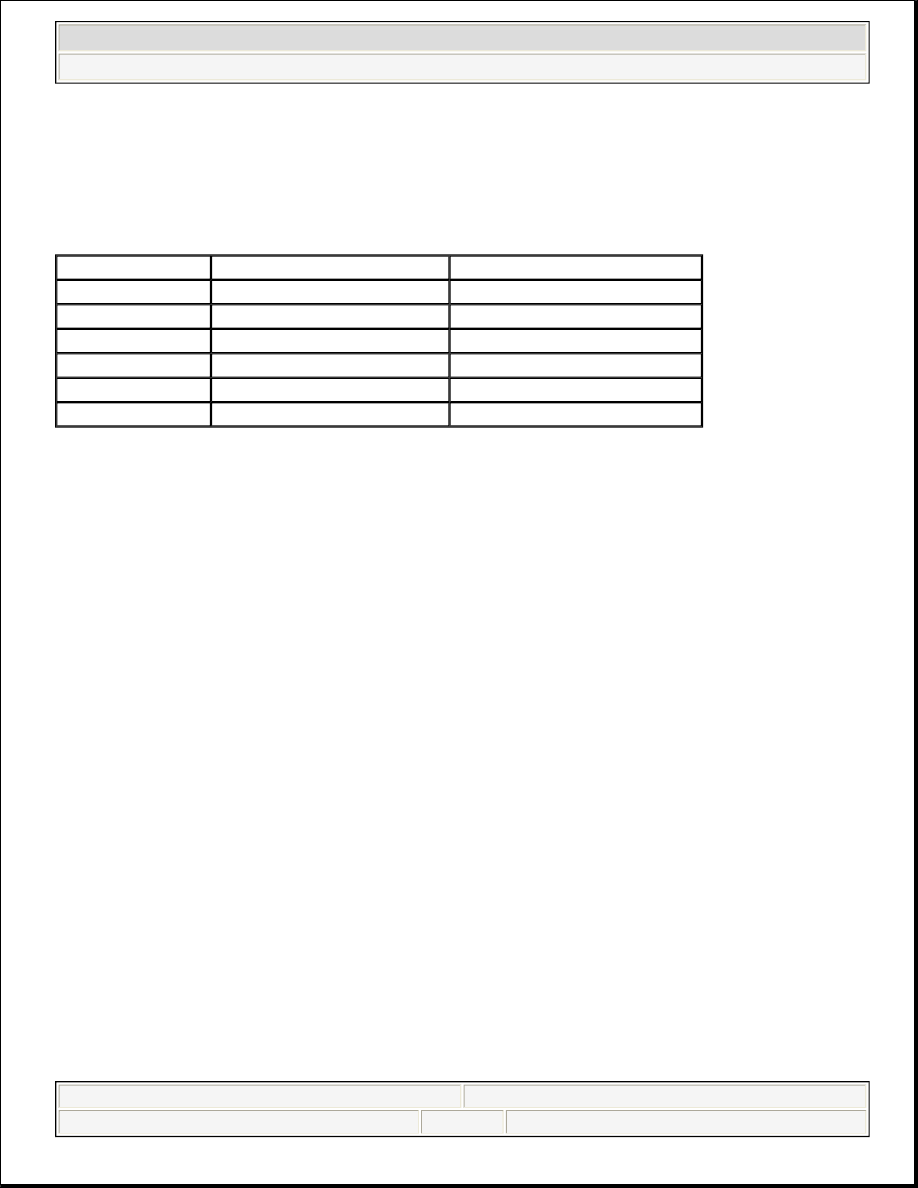
Measure the battery voltage at the battery terminals. Refer to the following table to determine the SOC 
according to the estimated battery temperature:  

BATTERY STATE OF CHARGE 

Use the SOC information as follows:  

z

A battery with a SOC that is below 65 percent must always be recharged before returning it to service or 
continuing storage.  

z

A battery with a SOC that is 65 percent or greater is generally considered to be charged enough in order 
to be returned to normal service or in order to continue storage. However, if the battery is being used in 
slow traffic or with short drive times, or if the temperature is very hot or very cold, the battery should be 
fully charged, to at least 90 percent, before returning it to service or continuing storage.  

CHARGING TIME REQUIRED 

The time required to charge a battery will vary depending upon the following factors:  

z

The battery charger capacity - The higher the charger amperage, the less time it will take to charge the 
battery.  

z

The SOC of the battery - A completely discharged battery requires more than twice as much charging 
time as a half charged battery. In a discharged battery with a voltage below 11 volts, the battery has a 
very high internal resistance and may only accept a very low current at first. Later, as the charging current 
causes the acid content to increase in the electrolyte, the charging current will increase. Extremely 
discharged batteries may not activate the reversed voltage protection in some chargers. Refer to the 
manufacturer's instructions for operating this circuitry.  

z

The temperature of the battery - The colder the battery is, the more time it takes to recharge the battery. 
The charging current accepted by a cold battery is very low at first. As the battery warms, the charging 
current will increase.  

CHARGING PROCEDURE 

for 12 hours. 

Battery Voltage 

% Charge At 0°C (32°F) 

% Charge At 25°C (75°C) 

12.75 V 

100% 

100% 

12.70 V 

100% 

90% 

12.60 V 

90% 

75% 

12.45 V 

75% 

65% 

12.20 V 

65% 

45% 

12.00 V 

40% 

20% 

NOTE:

Turn OFF the ignition when connecting or disconnecting the battery cables, the 
battery charger or the jumper cables. Failure to do so may damage the PCM or 
other electronic components. 


2004 Hummer H2 

2004 STARTING & CHARGING SYSTEMS Starters - H2


When charging side-terminal batteries with the battery cables connected, connect the charger to the positive 
cable bolt and to a ground located away from the battery. When charging side-terminal batteries with the battery 
cables disconnected, install the battery side terminal adapters and connect the charger to the adapters.  

Tighten the battery side terminal adapters to 15 N.m (11 lb ft). Use the following procedure to charge the 
battery:  

1. Turn OFF the charger.  

2. Ensure that all of the battery terminal connections are clean and tight.  

3. Connect the charger positive lead to the battery positive terminal on the battery or the remote jumper stud 

underhood.  

4.  

Connect the negative charger lead to a solid engine ground or to a ground stud in the engine compartment 
that is connected directly to the battery negative terminal, but away from the battery. If the negative 
battery cable is disconnected and a terminal adapter is being used, connect directly to the adapter.  

5. Turn ON the charger and set to the highest setting for normal charging.  

6. Inspect the battery every half hour after starting the battery charger. 

z

Charge the battery until the taper-rate charger indicates that the battery is fully charged.  

z

Estimate the battery temperature by feeling the side of the battery. If it feels hot to the touch or its 
temperature is over 45°C (125°F), discontinue charging and allow the battery to cool before 
resuming charging.  

7. After charging, test the battery. Refer to BATTERY INSPECTION/TEST (NON-HP2) .  

BATTERY ELECTRICAL DRAIN/PARASITIC LOAD TEST 

Tools Required: J-38758 Parasitic Draw Test Switch  

Diagnostic Aids 

z

Be sure to rule out any possible obvious influences, such as customer error or aftermarket equipment.  

z

Customer driving habits, such as regular short trips. This does not allow enough time to properly charge 

NOTE:

Use the correct fastener in the correct location. Replacement fasteners must be 
the correct part number for that application. Fasteners requiring replacement or 
fasteners requiring the use of thread locking compound or sealant are identified 
in the service procedure. Do not use paints, lubricants, or corrosion inhibitors 
on fasteners or fastener joint surfaces unless specified. These coatings affect 
fastener torque and joint clamping force and may damage the fastener. Use the 
correct tightening sequence and specifications when installing fasteners in 
order to avoid damage to parts and systems. 

NOTE:

Do not connect the negative charger lead to the housings of other vehicle 
electrical accessories or equipment. The action of the battery charger may 
damage such equipment. 


2004 Hummer H2 

2004 STARTING & CHARGING SYSTEMS Starters - H2


the battery.  

z

Verify that the battery and charging system are in proper working order. Refer to BATTERY 
DIAGNOSIS & SERVICING 
.  

z

A battery discharging for no apparent reason while the vehicle is parked can be caused by an intermittent 
draw, such as a module waking up, or a continuous draw, such as a dome light or stuck relay.  

z

Some systems and modules such as OnStar(R), and regulated voltage control (RVC), if equipped, are 
designed to wake-up, perform a task, and go back asleep at regular intervals. Refer to Body Control 
Module for the system or modules description and operation.  

z

Remote keyless entry (RKE) will wake up due to an outside input. Refer to Keyless Entry System.  

z


The battery run down time will vary depending on cold cranking amperage (CCA) and reserve capacity 
(RC). If the CCA and RC are higher, then the battery run down time would be longer. If the CCA and RC 
are lower, then the battery run down time would be shorter. The graph below indicates roughly how many 
days a 690 CCA battery with at 110 min. RC (60.5 AH) starting at 80 percent state of charge will last 
with a constant current draw until it reaches 50 percent state of charge. Differences in battery rating and 
temperature will affect the results.  

BATTERY RUN-DOWN RATING 

Diagnostic Procedures 

NOTE:

The battery specification listed below is a generic specification. Refer to 
BATTERY USAGE when testing the battery. 

Current Drain 

Days 

25 mA 

30.5 

50 mA 

16.5 

75 mA 

11 

100 mA 

8.25 

250 mA 

3.3 

500 mA 

1.65 

750 mA 

1 A 

0.8 

2 A 

0.4 

NOTE:

Do not turn the parasitic draw test switch to the OFF position with the engine 
running. Damage will occur to the vehicle's electrical system. 

NOTE:

The test switch must be in the ON position when removing the fuses in order to 
maintain continuity in the electrical system. This avoids damaging the digital 
multimeter due to accidental overloading, such as a door being opened to 
change a fuse. 


2004 Hummer H2 

2004 STARTING & CHARGING SYSTEMS Starters - H2


1. Disconnect the battery negative cable from the battery negative terminal.  

2. Install the male end of the J-38758 to the battery ground terminal.  

3. Turn the J-38758 knob to the OFF position.  

4. Install the battery negative cable to the female end of the J-38758.  

5. Connect a 10A fused jumper wire to the test switch tool terminals.  

6. Turn the J-38758 knob to the ON position.  

7. Road test the vehicle and activate ALL of the accessories, including the radio and air conditioning. This 

may take up to 30 minutes.  

8. Park the vehicle. Turn the ignition switch to the OFF position and remove the ignition switch key.  

9. Turn the J-38758 knob to the OFF position. The current now flows through the jumper wire.  

10. Wait 1 minute. If the fuse blows, install an inductive ammeter and go to step 20.  

11. Remove the fused jumper wire.  

12. Set a digital multimeter to the 10A scale.  

13. Connect the digital multimeter to the test switch tool terminals.  

14. Turn the J-38758 knob to the OFF position. The current flows now through the digital multimeter.  

15. Wait 1 minute. Check and record the current reading. 

A. When there is a current reading on 2A or less, turn the J-38758 knob to the ON position. The 

electrical current will now pass through the switch.  

B. Then switch the digital multimeter down to the 2A scale for a more accurate reading when the J-

38758 knob is turned OFF.  

16. Turn the J-38758 knob to the OFF position. Wait 15 minutes for most vehicles.  

17. Check and record the current reading.  

18. Note the battery reserve capacity, amp hour rating. Refer to BATTERY USAGE 

A. Divide the reserve capacity by 4, amp hour rating by 2.4.  

B. Compare this to the multimeter milliampere reading taken in the previous step. The parasitic 

current drain should not exceed this number. Example: If a battery has a reserve capacity of 100 
minutes, (60 A/H) the current drain should not exceed 25 mA.  

19. If excessive current drain is not found at this time and there are no other apparent causes, go to next step.  

20. Using the MIN/MAX function of the digital multimeter, monitor the parasitic drain overnight or during 

the day. This will determine if something has been activated during that time frame.  

21.  

NOTE:

The switch knob (1) on the J-38758 is marked ON and OFF. When the switch 
knob is in the ON position, the circuit is closed and electrical current will pass 
through the switch. When the switch knob is in the OFF position, the circuit is 
open and electrical current will not pass through the switch. 

NOTE:

The test switch must be in the ON position when removing the fuses in 
order to maintain continuity in the electrical system. This avoids damaging 
the digital multimeter due to accidental overloading, such as a door being 


2004 Hummer H2 

2004 STARTING & CHARGING SYSTEMS Starters - H2


Content   ..  1149  1150  1151  1152   ..