Hummer H2. Manual - part 1144


  Index      Hummer     Hummer H2 - service repair manual 2004 year


Search            


Content   ..  1142  1143  1144  1145   ..


Hummer H2. Manual - part 1144


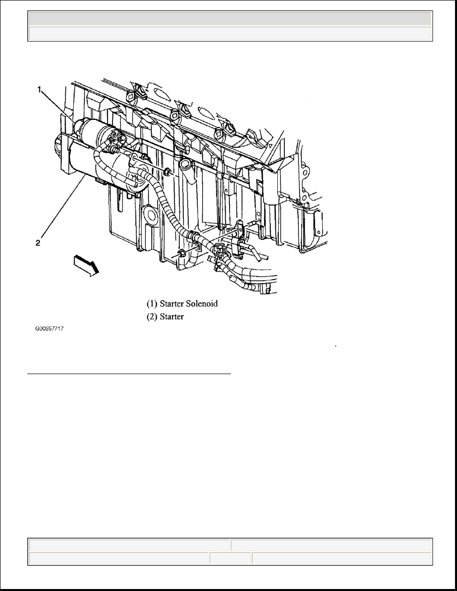
Fig. 3: Locating Starter Assembly & Starter Solenoid 
Courtesy of GENERAL MOTORS CORP. 

ENGINE ELECTRICAL CONNECTOR END VIEWS


2004 Hummer H2 

2004 STARTING & CHARGING SYSTEMS Starters - H2


Fig. 4: Identifying Ignition Switch Harness Connector Terminals 
Courtesy of GENERAL MOTORS CORP.


2004 Hummer H2 

2004 STARTING & CHARGING SYSTEMS Starters - H2


Fig. 5: Identifying Park/Neutral Switch Harness Connector Terminals 
Courtesy of GENERAL MOTORS CORP. 

DIAGNOSTIC STARTING POINT - ENGINE ELECTRICAL 

Begin the system diagnosis with the Diagnostic System Check - Engine Electrical. See DIAGNOSTIC 
SYSTEM CHECK - ENGINE ELECTRICAL 
. The Diagnostic System Check will provide the following 
information:  

z

The identification of the control module(s) which command the system.  

z

The ability of the control module(s) to communicate through the serial data circuit.  

z

The identification of any stored diagnostic trouble codes (DTCs) and their status.  

The use of the DIAGNOSTIC SYSTEM CHECK - ENGINE ELECTRICAL will identify the correct 
procedure for diagnosing the system and where the procedure is located.  

DIAGNOSTIC SYSTEM CHECK - ENGINE ELECTRICAL 

1. Did you perform the Battery Inspection/Test? If yes, go to next step. If no, go to BATTERY 

INSPECTION/TEST (NON-HP2) 


2004 Hummer H2 

2004 STARTING & CHARGING SYSTEMS Starters - H2


2. Install a scan tool. Does the scan tool power up? If yes, go to step 4 . If no, go to SCAN TOOL DOES 

NOT POWER UP .  

3.  

Access the Class 2 Power Mode in the Diagnostic Circuit Check on the scan tool. Rotate the ignition 
switch through all positions while observing the ignition switch power mode parameter. Does the ignition 
switch parameter reading match the ignition switch position for all switch positions? If yes, go to next 
step. If no, go to POWER MODE MISMATCH .  

4. Turn ON the ignition, with the engine OFF. Attempt to communicate with each module on the class 2 

serial data circuit. If using a Tech 2, obtain this information using the Class 2 Message Monitor feature. 
Does the scan tool communicate with any module on the class 2 serial data circuit? If yes, go to next step. 
If no, go to Scan Tool Does Not Communicate with Class 2 Device in BODY CONTROL MODULES  

5. Select the Display DTCs function for each module. If using a Tech 2, use the Class 2 DTC Check feature 

in order to determine which modules have DTCs set. Record all of the displayed DTCs the DTC status 
and the module which set the DTC. Does the scan tool display any DTCs? If yes, go to next step. If no, 
go to SYMPTOMS - ENGINE ELECTRICAL .  

6. Does the scan tool display any DTC beginning with "U"? If yes, go to Diagnostic Trouble Code (DTC) 

List. If no, go to next step.  

7. Does the scan tool display any DTC beginning with "P"? If yes, go to Powertrain DTC list in Engine 

Controls. If no, go to next step.  

8. Does the scan tool display any DTC beginning with "B"? If yes, go to Diagnostic Trouble Code (DTC) 

List.  

BATTERY INSPECTION/TEST (NON-HP2) 

Diagnostic Aids 

z

If testing the vehicle with the battery cables still connected, wiggle the J-42000 clips on the terminal bolt. 
This may cut through any coating or through any oxidation that may be present on the bolt. Even new 
bolts contain a protective coating that may insulate or cause a resistance in the test circuit.  

z

If correct connections to the battery terminal bolts in the vehicle are in doubt, perform the following 
steps: 

A. Disconnect the negative battery cable.  

B. Disconnect the positive battery cable.  

C. Install the test adapters on the terminals.  

D. Follow the instructions for testing a removed battery.  

z

If the tester displays a REPLACE BATTERY or BAD CELL-REPLACE result for a battery tested in the 
vehicle with the battery cables connected, perform the following steps: 

NOTE:

The engine may start during the following step. Turn OFF the engine as 
soon as you have observed the Crank power mode. 

NOTE:

Follow these instructions in order to avoid an incorrect diagnosis because of 
connections: 


2004 Hummer H2 

2004 STARTING & CHARGING SYSTEMS Starters - H2


Content   ..  1142  1143  1144  1145   ..