Content .. 1080 1081 1082 1083 ..
Hummer H2. Manual - part 1082
SELF DIAGNOSTIC SYSTEM
RETRIEVING DIAGNOSTIC TROUBLE CODES
See RETRIEVING DIAGNOSTIC TROUBLE CODES under SELF-DIAGNOSTIC SYSTEM under
appropriate SELF-DIAGNOSTICS article in ENGINE PERFORMANCE.
CLEARING DIAGNOSTIC TROUBLE CODES
See CLEARING DIAGNOSTIC TROUBLE CODES under SELF-DIAGNOSTIC SYSTEM under appropriate
SELF-DIAGNOSTICS article in ENGINE PERFORMANCE.
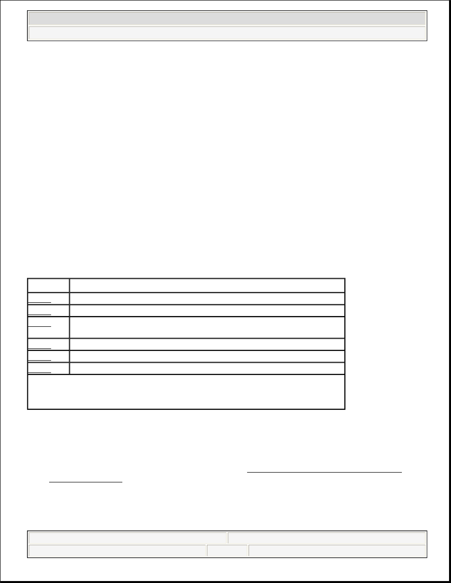
DIAGNOSTIC TROUBLE CODE DEFINITIONS
DIAGNOSTIC TROUBLE CODE DEFINITIONS
DIAGNOSTIC TESTS
DTC P0562: LOW SYSTEM VOLTAGE
1. If diagnostic system check was not performed, perform ENGINE ELECTRICAL DIAGNOSTIC
SYSTEM CHECK under ON-VEHICLE TESTING. If diagnostic system check was performed, go to
next step.
2. Using scan tool, observe Ignition 1 Signal voltage in Powertrain Control Module (PCM) data list. If
voltage is 10.5 volts or less, go to next step. If voltage is greater than 10.5 volts, go to step 4 .
3. Test ignition feed circuit to PCM for high resistance or an open. If problem exists, repair as necessary.
NOTE:
Diagnostic trouble code tests are written specifically for use with GM Tech I or
Tech II scan tools. Generic scan tool can be used but may have limited
functions. This article only covers the portion of those systems which relates to
charging system diagnosis. For further information, see appropriate SELF-
DIAGNOSTICS article in ENGINE PERFORMANCE.
DTC
(1)
Description
P0562
Low System Voltage
P0563
High System Voltage
P0615
Improper Voltage Level On The Output Circuit That Controls The Starter
Relay
P0622
Out-Of-Range Duty Cycle Signal
P1637
Generator Turn-On Signal Circuit Voltage Out-Of-Range
P1638
Out-Of-Range Duty Cycle Signal
(1)
Codes listed in this table are only for testing covered in this article. For complete
DTC listing, see appropriate BODY CONTROL MODULES article in
ACCESSORIES & EQUIPMENT.
2004 Hummer H2
2003-04 STARTING & CHARGING SYSTEMS Generators & Regulators - H2