Hummer H1 (2006+). Manual - part 413
 

  Index      Hummer     Hummer H1 DMAX - service repair manual 2006 year


Search            


Content   ..  411  412  413  414   ..


Hummer H1 (2006+). Manual - part 413


13-26

Accessories

_____________________________________________________________

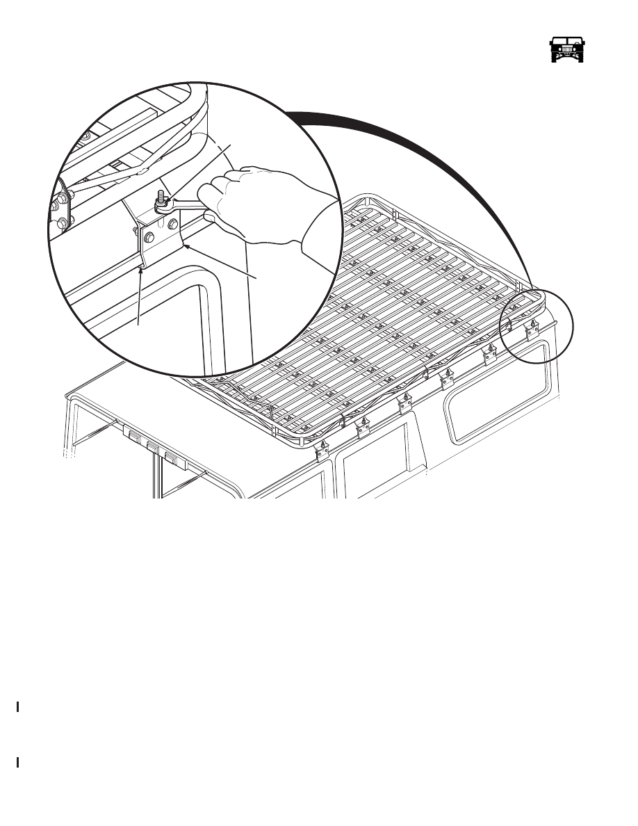
Figure 13-37:   Roof Rack Clamp

Installation

CAUTION: Clamps are made of aluminum. Overtightening may cause the clamps to crack.

1.

With the help of an assistant, place the rack assembly on the rain gutters of the vehicle and adjust it for the best load carrying position, 
while staying within the confines of the roof edges (Figure  13-37).

2.

Cut pieces of foam tape to fit the lower section of the “L” bracket and place on the inside lower portion of the brackets. Reinstall the
“L” brackets on the clamp assemblies and lightly snug the “L” bracket retaining bolts.

3.

Alternate from side to side and tighten the adjusting nut of each clamp assembly until the clamp assemblies are secure in the rain
gutters.

Roof Rack Floor Piece Replacement

Removal

1.

Remove the bolts, lockwashers and the nuts holding the floor piece to the mounting points (Figure  13-38).

2.

Remove the floor piece. 

Installation

1.

Align the floor rail assemblies to have a equal distacne between each assembly and tihgten the hardware to 20-25 lb-ft (27-34 
N•m).

00-S13-020.1

FOAM

TAPE

INSIDE

“L” BRACKET

ADJUSTING

NUT

6-1-05

____________________________________________________________

 Accessories  13-27

5745804

Figure 13-38:   Floor Rail and Clamp Assembly

Roof Rack Crossbar Replacement

Removal

1.

Remove the roof rack from the vehicle.

2.

Remove the floor pieces from the roof rack.

3.

Remove the locknuts, washers, bolts, washers, and the crossbar from the sides  (Figure  13-39).

Installation

1.

Install the crossbar on the sides with the washers, bolts, washers, and the locknuts. Tighten the locknuts to 25 lb-ft 
(34 N•m) (Figure  13-39).

2.

Install the floor pieces on the roof rack.

00-S13-019.1

CLAMP

ASSEMBLY

CROSS
BRACE

FLOOR

RAIL

ASSEMBLY

6-1-05

13-28

Accessories

_____________________________________________________________

3.

Install the roof rack onto the vehicle.

Roof Rack End Replacement

Removal

Remove the bolts, locknuts, and the rack end from the sides (Figure  13-39).

Installation

Install the rack end with the hardware and tighten the nuts to 20-20 lb-ft (27-34 N•m) (Figure  13-39).

Figure 13-39:   End and Center Assembly Layout

SOFT SLANT BACK (MODEL 90)

Removal

1.

Unzip the forward portion of the slant back cover from the soft top cover.

2.

Release the hook and loop the fasteners on the lower sides and the lower rear of the slant back cover.

3.

Release the hook and the loop fasteners on the inside of the cover securing the cover to the support structure.

4.

Remove the slant back cover from the slant back support assembly.

5.

Release the hook and the loop straps securing the formers to the support structure and remove the formers.

6.

Loosen the support structure retaining straps and release the strap hooks from the footman loops.

7.

Remove the screws securing the hinge brackets to the wheel houses and remove the support structure.

00-S13-018

6-1-05

____________________________________________________________

 Accessories  13-29

5745804

Figure 13-40:   Soft Slant Back R & I.

Installation

1.

Place the support structure on the wheelhouses and install the screws through the hinge brackets into the wheelhouses.

2.

Insert the retaining strap hooks in the footman loops and adjust the retaining straps.

3.

Place the formers on the forward top corners of the support structure and secure with the hook and loop straps.

4.

Engage the hook and loop fasteners on the inside of the cover.

5.

Place the cover on the support structure and zip the forward edge to the soft top cover.

6.

Pull the rear edge of the cover tight and engage the hook and loop on the tailgate.

7.

Pull the sides of the cover tight and engage the hook and loop on the sides of the wheelhouses.

FOOTMAN

LOOP

HINGE

BRACKET

SUPPORT

STRUCTURE

STRAP

COVER

FORMER

6-1-05


Content   ..  411  412  413  414   ..