Hummer H1 (2006+). Manual - part 410
13-14
Accessories
_____________________________________________________________
4.
Remove the clamps from the motor.
5.
Place the winch on the end with the motor end up (Figure 13-25).
6.
Remove the two bolt assemblies and the rear cover from the motor housing.
NOTE: Perform steps 7 through 11 only if replacing the brush assembly.
7.
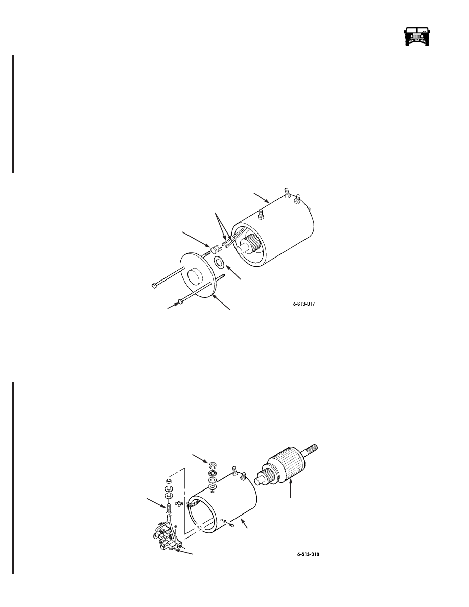
Remove the electric thermal switch from the two electric thermal switch leads.
8.
Remove the motor housing from the drum support and the armature assembly from the brush assembly (Figure 13-24).
9.
Remove the nut, lockwasher, washer, and the insulator securing the brush assembly power stud to the motor housing. Discard
the lockwasher.
10. Remove the three nuts, screws, and the brush assembly from the motor housing.
11. Remove the spacer, insulator, and the washer from the brush assembly power stud.
Figure 13-23: Motor and Gasket
Installation
NOTE: Do not apply coating to any electrical contacts of the armature assembly. Perform steps 1 through 5 only if replacing brush
assembly.
1.
Install the washer, insulator, and the spacer on the brush assembly power stud (Figure 13-24).
2.
Install the brush assembly in the motor housing with the three screws and the nuts
3.
Secure the brush assembly power stud to the motor housing with the insulator, washer, lockwasher, and the nut.
4.
Coat the armature shaft with lubricant and install in the brush assembly.
5.
Coat the head of the electric thermal switch with lubricant and connect to the two electric thermal switch leads (Figure 13-23).
.
Figure 13-24: Brush Assembly and Armature Assembly
REAR COVER
SPACER
ELECTRIC THERMAL
SWITCH
ELECTRIC THERMAL
SWITCH LEADS
MOTOR
HOUSING
BOLT
ASSEMBLY
SPACER
MOTOR
HOUSING
ARMATURE
ASSEMBLY
BRUSH
BRUSH
POWER
ASSEMBLY
ASSEMBLY
STUD
6-1-05