Hummer H1 (2006+). Manual - part 360
12-116
Electrical System
______________________________________________________
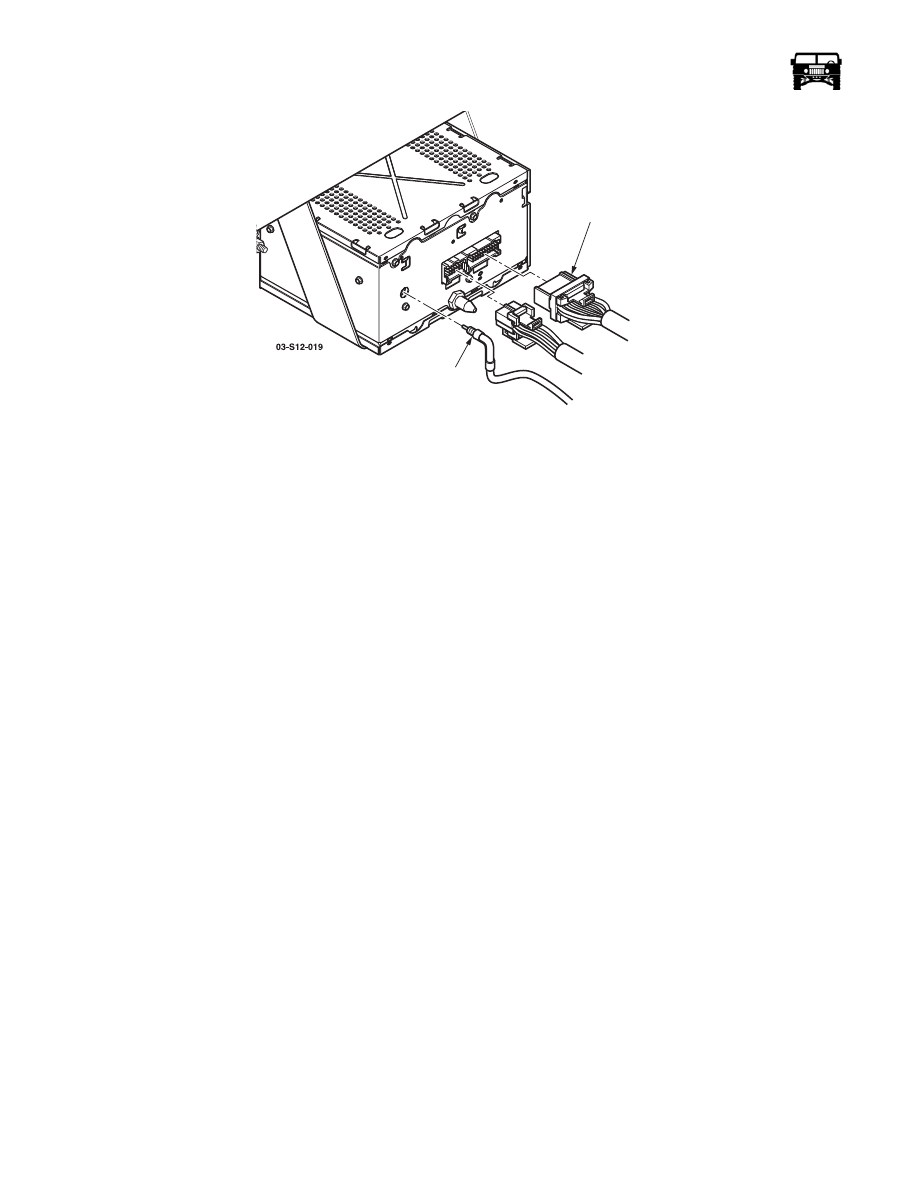
Figure 12-80: Audio Harness Connections.
DIAGNOSIS -AUDIO SYSTEM
1.
Verify the customer complaint.
2.
Follow the radio service procedures.
3.
If any technical service is required, have all the pertinent information ready before placing the call.
NOTE: Before performing any diagnostic procedures or using any diagnostic tools, check wiring schematics for component cir-
cuitry to determine the location of fuses and circuit breakers in the circuit. Fuses and circuit breakers must be in good working or-
der to perform proper diagnostic procedures.
Audio System Diagnostic Kit J–39916-A is available from Kent-Moore. The kit contains a diagnostic CD and cassette, a head
cleaner cassette and instructions. This kit is designed to isolate the type of malady and the area of its origin by producing tones of
various frequencies. By adjusting the fade and balance, a technician can evaluate the sound quality produced in different areas of
the system.
Identifying Concerns
• Check for technical service bulletins.
• For reception concerns, determine if the station is obtainable in the customers listening area.
• To test for audio reception/noise, position the vehicle outside the building with the hood down.
• Duplicate the customers complaint before trying to diagnose the system. Have the customer demonstrate the condition. Test
drive the vehicle with the customer and then test drive another similar model vehicle (with a similar audio system) to do a
comparison of the two vehicles to determine if the condition is abnormal.
• Before diagnosing, identify components, their features and the customer’s complaint.
• Determine if any aftermarket equipment is installed on the vehicle. Disconnect the aftermarket equipment and determine if
the customers complaint still exists.
• Perform the following steps to identify a noisy component:
1.
Identify the ignition switch key position in which the noise appears, such as: accessory, key on engine not running, and key on
engine running.
2.
Remove the fuses one at a time until the complaint condition has been eliminated.
3.
Mark the complaint fuse(s) and reinstall all the fuses and circuit breakers.
4.
Identify all the systems and the components powered by the complaint fuse(s).
5.
Disconnect the components powered by the complaint fuse(s) one at a time until the complaint condition has been eliminated
and the noisy component has been identified.
AUDIO
ANTENNA LEAD-IN
HARNESS