Hummer H1 (2006+). Manual - part 353
 

  Index      Hummer     Hummer H1 DMAX - service repair manual 2006 year


Search            


Content   ..  351  352  353  354   ..


Hummer H1 (2006+). Manual - part 353


12-88

Electrical System

_______________________________________________________

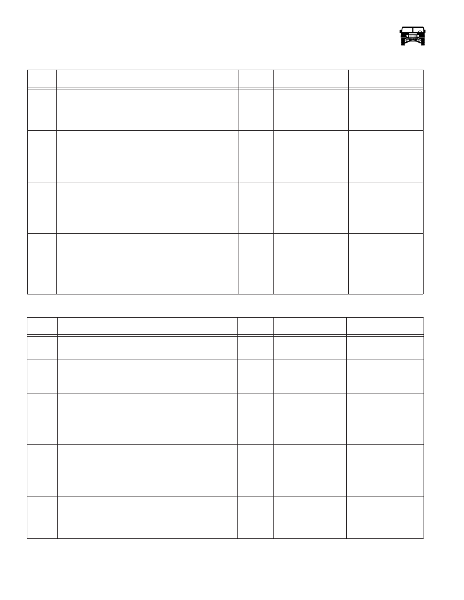
 Power Windows Inoperative, All Windows  (Figure 12-156)

Step

Action

Value(s)

Yes

No

1.

Remove relay R4 from the interior fuse box. With a 
DVOM, check the black wire (CKT 59) for resistance to 
ground. Does the resistance meet the specified value?

<.2

1

Go to step 2.

Repair the open or bad 

connection in CKT 59 

between relay R4 and 

Ground G4.

2.

With a DVOM, check the voltage on the blue wire (CKT 
175) at R4. Is the specified voltage present?

+12v

Go to step 3.

Repair the open or bad 

connection in CKT 175 

between R4 and fuse 

5M in the exterior fuse 

box.

3.

Turn the ignition switch to the “Run” position. With a 
DVOM, check the voltage on the dark green wire (CKT 
296) at R4. Is the specified voltage present?

+12v

Go to step 4.

Repair the open or bad 

connection in CKT 296 

between R4 and fuse 

2G in the interior fuse 

box.

4.

Remove the drivers door window switch and harness from 
the bezel. Disconnect the power window switch from the har-
ness. With a DVOM, check the resistance between the red 
wire (CKT 171) on the drivers power window switch harness 
and the red wire (CKT 171) at R4 of the interior fuse box. 
Does the resistance meet the specification?

<.2

1

Replace relay R4 in the 

interior fuse box.

Repair the open or bad 

connection in CKT 

171 between the driv-

ers window switch and 

R4.

 Power Windows Only Operate Using The Console Switches

Step

Action

Value(s)

Yes

No

1.

Does the drivers door window operate as designed? 

–––

Go to step 2.

Refer to the proper 

chart.

2.

If the window lock out switch is in the “Lock” position 
move it to the “Unlock” position. Are the power win-
dows operating as designed? 

–––

No further repair is 

needed at this time.

Go to step 3.

3.

Gain access to the power window switches on the con-
sole. With a DVOM, check for a ground at each of the 
black wires (CKT 56) on all three power window 
switches. Do all six wires meet with the specified value 
for resistance to ground?

<.2

1

Go to step 4.

Repair the open or bad 

connection between the 

power window switches 

and ground G4.

4.

Turn the ignition switch to the “Run” position. With a 
DVOM, back probe the purple wire (CKT 222) on the 
power window lock out switch. Make sure the switch is 
in the “Unlock” position. Is the specified voltage 
present?

+12v

Refer to the individ-

ual window charts.

Go to step 5.

5.

With the ignition still in the “Run” position check the 
voltage on the red wire (CKT 171) of the power window 
lockout switch harness. Is the specified voltage present?

+12v

Replace the power 

window lock out 

switch.

Repair the open or bad 

connection between the 

power lock out switch 

and relay R4.

______________________________________________________

 Electrical System  12-89

 Passenger Front Door Power Window Inoperative

Step

Action

Value(s)

Yes

No

1.

Do all the other windows operate as designed?

––-

Go to step 2.

Refer to the 

proper chart.

2.

Gain access to the passenger front power window 
switch harness. Turn the ignition switch to the run 
position. With a DVOM, check the voltage at the 
purple wire (CKT 170). Is the specified voltage 
present?

+12v

Go to step 3.

Repair the open 

or bad connection 

in CKT 170 
between the 

power window 

switch and the 

power window 

lock out switch.

3.

Disconnect the power window switch from the 
harness. Using a DVOM, check for resistance to 
ground on the orange wire (CKT 314) and the 
dark blue wire (CKT 313). Does the resistance 
meet the specifications?

<.2

1

Go to step 4.

Repair the open 

or bad connection 

on CKT 313 or 

314 between the 

passenger door 

window switch 

and the console 

window switch.

4.

Connect the power window switch to the harness 
and make sure that the ignition switch is in the run 
position. With a DVOM, back probe the red wire 
(CKT 227) and the yellow wire (CKT 226) at the 
same time. Check the voltage while operating the 
switch from “Up” to “Down”. Is the specified volt-
age present and does the polarity change from posi-
tive to negative with the action of the switch?

+12v to -12v

Go to step 5.

Replace the   

passenger front

power window 

switch.

5.

Gain access to the power window motor and dis-
connect the harness. With a DVOM, back probe 
the red wire (CKT 227) and the yellow wire 
(CKT 226). Operate the power window switch 
and watch the voltage. Is the specified voltage 
present and does it change from positive to nega-
tive with the action of the switch.

+12v to -12v.

Replace the pas-

senger front 

window motor.

Repair the open 

or bad connection 

on either CKTs 

226 or 227 

between the 

power window 

motor and 

switch.

 (Passenger/Drivers) Rear Door Power Window Inoperative

NOTE: Refer to the wiring diagram for the circuit numbers.

Step

Action

Values

Yes No

1.

Do all the other windows operate as designed?

––-

Go to step 2.

Refer to the 

proper chart.

12-90

Electrical System

_______________________________________________________

2.

Gain access to the right rear power window 
switch harness. Turn the ignition switch to the run 
position. With a DVOM, check the voltage at the 
purple wire (CKT 170). Is the specified voltage 
present?

+12v

Go to step 3.

Repair the open 

or bad connection 

in CKT 170 
between the 

power window 

switch and the 

power window 

lock out switch.

3.

Disconnect the power window switch from the 
harness. Using a DVOM, check for resistance to 
ground on the brown (CKT 319) wire and the 
light green wire (CKT 320) Does the resistance 
meet the specifications?

<.2

1

Go to step 4.

Repair the open 

or bad connection 

on (CKT 319) or 

(CKT 320)

between the door 

window switch 

and the console 

window switch.

4.

Connect the power window switch to the harness 
and make sure that the ignition switch is in the run 
position. With a DVOM, back probe terminals 1 and 
5 at the same time. Check the voltage while operat-
ing the switch from “Up” to “Down”. Is the speci-
fied voltage present and does the polarity change 
from positive to negative with the action of the 
switch?

+12v to -12v

Go to step 5.

Replace the     

power window 

switch.

5.

Gain access to the power window motor and dis-
connect the harness. With a DVOM, back probe 
the red wire (CKT 227) and the yellow wire 
(CKT 226), Operate the power window switch 
and watch the voltage. Is the specified voltage 
present and does it change from positive to nega-
tive with the action of the switch.

+12v to -12v.

Replace the 

window motor.

Repair the open 

or bad connection 

on (CKT  227) or 

(CKT 226) 

between the 

power window 

motor and 

switch.

 (Passenger/Drivers) Rear Door Power Window Inoperative

NOTE: Refer to the wiring diagram for the circuit numbers.

Step

Action

Values

Yes No

______________________________________________________

 Electrical System  12-91

POWER DOOR LOCKING AND KEYLESS ENTRY SYSTEM

System Description

Operation of the power door locks starts with activation of the door lock switch or remote transmitter (Figure 12-61). A signal is
received by the remote keyless entry module. The module will then activate the door locks. 

The keyless entry system allows convenient operation of the vehicle door locks from a distance. Equipped vehicles are supplied
with two, three button remote transmitters used to operate the system. Two additional remote transmitters can be added.

Figure 12-61:   Door Lock Switch and Remote

 Power Door Lock Switch Replacement

NOTE: Switch replacement is the same for all doors.

Removal

1.

Remove the screws, and the bezel (Figure 12-62).

2.

Disconnect the console harness from the switch.

3.

Separate the switch from the mounting plate.

Installation

1.

Install the switch in the bezel.

2.

Connect the switch to the console harness.

3.

Install the switch in the bezel and secure with the screws.

Figure 12-62:   Power Door Lock Switch Mounting

Power Door Lock Actuator Replacement

Removal

NOTE: Actuator replacement is the same for all doors.

DOOR LOCK SWITCH

REMOTE TRANSMITTER

BEZEL

SWITCH

HARNESS


Content   ..  351  352  353  354   ..