Hummer H1 (2006+). Manual - part 321
 

  Index      Hummer     Hummer H1 DMAX - service repair manual 2006 year


Search            


Content   ..  319  320  321  322   ..


Hummer H1 (2006+). Manual - part 321


11-18 Heating/Ventilation/Air Conditioning (HVAC)

______________________

PRESSURE HOSE TORQUE SPECIFICATIONS

CAUTION: To avoid potential thread or fitting damage, hand start connections before using wrenches. 

Air conditioning system fittings are a common source of refrigerant leaks. When service requires disconnecting and connecting fit-
tings, observe the following: 

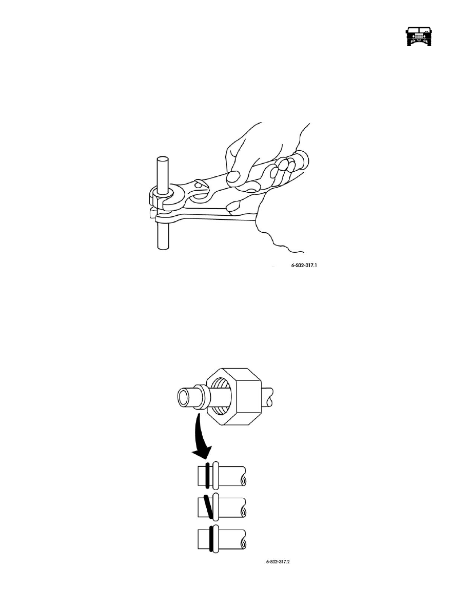
• When tightening or loosening hose and tube fittings, use two wrenches for equalized support (Figure  11-6). 

Figure 11-6:   Hose and Tube Fittings 

• Plug the open ends of hoses after disassembly. Do not remove the plugs from hose fittings until each component is ready for 

connection. This will prevent moisture and dirt contamination which can cause compressor wear and system blockage. 

• Make sure that O-rings are properly seated before assembly (Figure  11-7). 

• Carefully interlock male and female ends of hoses (Figure  11-8). 

• Before making any hose and tube connection, apply a few drops of refrigerant oil to the O-rings and threaded portions of the 

connector. Make connections quickly. 

• Tighten fittings to proper torque specification based on hose size. 

Figure 11-7:   Correct Seating O-Rings

INCORRECT

INCORRECT

PROPERLY

SEATED

_____________________

 Heating/Ventilation/Air Conditioning (HVAC)  11-19

Figure 11-8:   Proper Connection of Hose End

AIR CONDITIONING PRESSURE HOSE REPLACEMENT

WARNING:  Air conditioning system components are subject to high-pressure R-134a gas. Always discharge pres-
sure and contain refrigerant using approved service equipment. Use extreme care when handling R-134a. Direct
contact with skin may cause frostbite. Do not smoke in areas where R-134a is stored or used. Failure to follow these
warnings may result in serious injury.

CAUTION: Cover all open lines to prevent contamination.

Suction Manifold Hose Replacement

Removal

1.

Discharge the air conditioning system.

2.

Remove the air cleaner and the splash shield.

3.

Disconnect the auxiliary hose connection.

4.

Disconnect the suction hose from the expansion valve manifold, discard the O-ring (Figure  11-9).

5.

Disconnect the suction hose at the compressor discard the O-ring (Figure  11-10).

6.

Remove the hose assembly from the vehicle.

Pressure Hose Torque Values

Hose Size

Torque

(Ft. Lb.)

Torque

(Newton Meters)

Minimum

Maximum

Minimum

Maximum

#6 Liquid 
Hose

11

13

15

17

#8 Dis-
charge 
Hose

15

20

20

27

#10 Suction 
Hose

21

27

28

36

#12 Suction 
Hose

24

28

33

38

FEMALE MALE

CORRECT

INCORRECT

 END

 END

11-20 Heating/Ventilation/Air Conditioning (HVAC)

______________________

Figure 11-9:   Suction Manifold Hose Removal

Installation

1.

Install the suction hose onto the expansion valve manifold block with a new O-ring.

2.

Torque the fitting to 21-27 lb-ft. (28-36 N•m).

3.

Install the auxiliary unit refrigerant line using a new O-ring.

4.

Torque the auxiliary unit line to 21-27 lb-ft. (28-36 N•m).

5.

Install the suction hose onto the compressor with a new O-ring and torque the bolt to 12 lb-ft. (16 N·m).

6.

Evacuate the system for 30 min.

7.

Recharge the system with 2lbs. 4oz. R134a.

8.

Performance test the A/C system.

9.

Install the air cleaner and the splash shield.

Discharge Hose Replacement

Removal

1.

Disconnect the discharge hose from the condenser. Remove and discard the O-ring (Figure  11-11).

LIQUID

SUCTION HOSE

EXPANSION VALVE

MANIFOLD BLOCK

AUXILIARY

OUTLETS

LINE

_____________________

 Heating/Ventilation/Air Conditioning (HVAC)  11-21

Figure 11-10:   A/C System

2.

Remove the P-clamp holding the line to the support bracket.

3.

Remove the discharge hose from the compressor and discard the O-ring (Figure  11-9). 

Installation

CAUTION: To avoid potential thread or fitting damage, hand start connections before using wrenches. 

1.

Position the O-ring on the discharge hose (Figure  11-9).

2.

Secure the discharge hose to the compressor with the bolt and torque to 12 lb-ft. (16 N·m). 

3.

Lubricate the O-ring and install the discharge hose to the condenser and torque the nut to 12 lb-ft. (16 N·m). 

4.

Install the driver side engine splash shield.

5.

Evacuate and charge the air conditioning system.

6.

Check for system leaks.

7.

Check the A/C operation.

Condenser-to-Receiver/Dryer Hose 

WARNING:  Air conditioning system components are subject to high pressure R-134a gas. Always discharge pres-
sure and contain refrigerant using approved service equipment. Use extreme care when handling R-134a. Direct
contact with skin may cause frostbite. Do not smoke in areas where R-134a is stored or used. Failure to follow these
warnings may result in serious injury.

CONDENSER

DISCHARGE HOSE

O-RING

P-CLAMP

RECEIVER

DRYER

EXPANSION VALVE

MANIFOLD BLOCK

OUTLETS

TO AUXILIARY

COMPRESSOR

SUCTION HOSE


Content   ..  319  320  321  322   ..