Hummer H1 (2006+). Manual - part 245
7-62
Brake System
_____________________________________________________________
Installation
1.
Install the brake line adapters in the same position as in the original modulator. Torque the 12 mm threaded adapter to 11 lb-ft
(15 N•m) and the 10 mm adapter to 9 lb-ft (12 N•m).
2.
Place the modulator alignment pin in the hole in the mounting bracket, install the two mount bolts and torque to 5 lb-ft (7
N•m).
3.
Connect the motor pump wire connector to the mounting bracket and install the assembly on the left air lift bracket with four
bolts, washers and lock washers. Torque the bolts to 28 lb-ft (38N•m).
4.
Connect the four wheel brake lines in their respective positions on the modulator and torque to 11 lb-ft (15 N•m).
5.
Connect the master cylinder hoses in their respective positions on the modulator and torque to 11 lb-ft (15 N•m).
6.
Connect the thirteen-pin, the two-pin and the one-pin wire connectors to the modulator assembly.
7.
Install the horn bracket and horns.
8.
Install the left front splash shield.
9.
Bleed the complete brake system.
10. Connect the batteries.
SPEED SENSOR REPLACEMENT
NOTE: The procedure for speed sensor replacement is basically the same for all four wheel ends.
WARNING: Connect speed sensors to the proper harness connectors. Connecting speed sensors to incorrect har-
ness connectors can cause the ABS/TT4 to malfunction.
Removal
1.
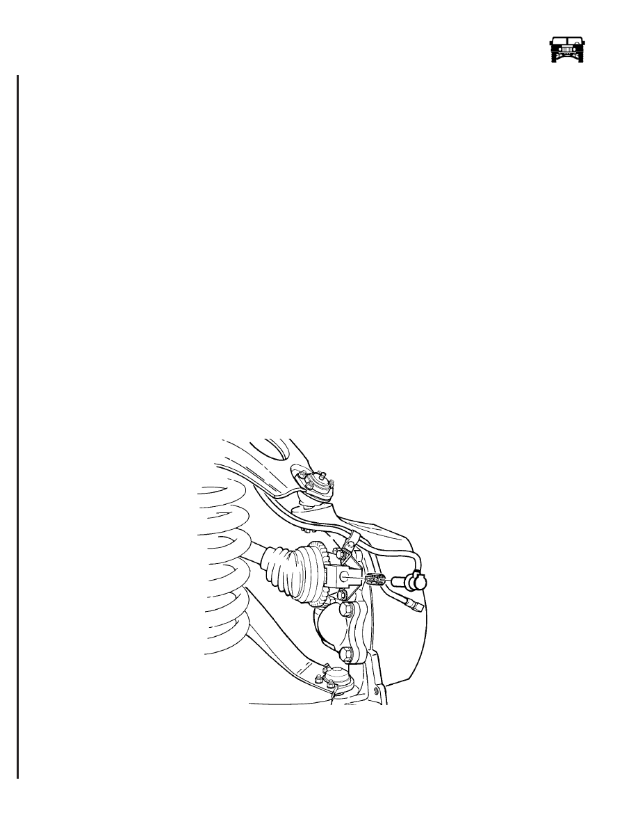
Rotate and pull the speed sensor head from the speed sensor mounting bracket and retaining sleeve (Figure 7-58).
2.
Remove and discard the speed sensor retaining sleeve.
Figure 7-58: Speed Sensor Removal
3.
Remove the speed sensor connector from the retaining clip near the top of the upper A-arm and disconnect the speed sensor
lead from the speed sensor harness (Figure 7-59).
4.
Remove the capscrews and clips securing the speed sensor lead to the A-arm and geared hub, and remove the sensor from the
vehicle.
6-1-05