Hummer H1 (2006+). Manual - part 241
7-46
Brake System
_____________________________________________________________
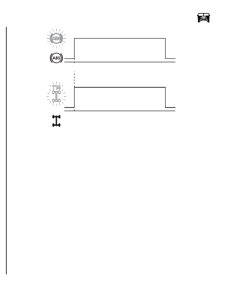
Figure 7-46: ABS/TT4 Warning Light Sequence.
Anti-lock braking operates by continually sensing the speed of each wheel. Wheel speed information is transmitted to an Electronic
Control Unit (ECU) which evaluates the information to determine when any wheel is about to lock. If locking commences, the
ECU transmits a control signal to the appropriate solenoid valve in the modulator controlling hydraulic pressure to the brake, thus,
brake pressure is adjusted to maintain wheel rotation.
The TorqTrac 4 system uses many of the same components as the ABS to control wheel spin when accelerating the vehicle on low
friction surfaces. Information from the wheel speed sensors is evaluated by the ECU which determines if a wheel is loosing traction
and spinning. The ECU actuates the modulator pump to provide hydraulic pressure which is modulated by the solenoid valves and
sent to the brake of the spinning wheel. This has the effect of transferring the torque to the non-spinning wheel on the higher fric-
tion surface. The system has an overheat protection feature which disables TT4 after 60 seconds of continuous use. This will be in-
dicated by a blinking TT4 lamp. TT4 will automatically return to normal operation after a 60 second cool down period.
ABS/TT4 DIAGNOSTICS
Fault Diagnostic Procedure
Faults are stored in the ECU memory in code form. The information can be retrieved by initiating and reading a series of flash and
pause sequences (blink codes) on the ABS warning light or with the Wabco Diagnostic Controller.
Use of the blink code procedure will determine the location of the fault prior to performing physical wiring and component tests,
thus reducing diagnostic time.
NOTE: An attempt to initiate the blink code diagnostic may result in a solid “on” ABS warning lamp without progressing to the
start phase of the diagnostic. If the above condition is present, remove the ABS Warning Lamp Relay from the exterior fuse box
and perform the blink code diagnostic (See Figure 7-61). After repairs are completed, replace the warning lamp relay in the socket.
Blink Code Procedure
To initiate the blink code procedure, connect the blink code switch jumper J–44237 to the Diagnostic Link Connector (DLC) of the
vehicle. The jumper allows you to short pin 4 to pin 15 of the DLC.
1.
Switch on the ignition, the ABS warning light will illuminate and extinguish if there are no active faults.
3 sec
ABS
Warning
Lamp
T T4 Info
Lamp
8-S07-002
ignition
on
T T4
3 sec
6-1-05