Hummer H1 (2006+). Manual - part 210
 

  Index      Hummer     Hummer H1 DMAX - service repair manual 2006 year


Search            


Content   ..  208  209  210  211   ..


Hummer H1 (2006+). Manual - part 210


5-80

Transmission/Transfer Case

_______________________________________________

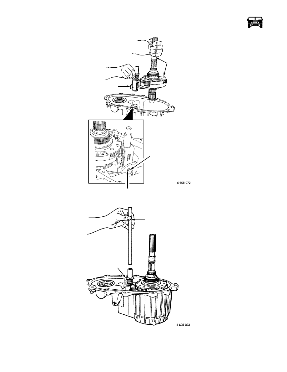
Figure 5-95:   Mainshaft, Differential, and Mode Fork Installation

Figure 5-96:   Shift Rail Installation

24. Assemble the driven sprocket and the front output shaft. Use a new snap ring if the old one is worn or distorted

(Figure 5-98).

MODE FORK

ASSEMBLY

MAINSHAFT AND

DIFFERENTIAL

ASSEMBLY

SECTOR

UPPER SLOT

MODE FORK PIN

MODE

FORK

SHIFT

RAIL

10-1-08

_______________________________________________

 Transmission/Transfer Case  5-81

5745804

25. Install the front output shaft, and the driven sprocket. Then install the drive chain (Figure  5-99).

26. Install the drive sprocket. Slide the sprocket down onto the mainshaft. Engage the sprocket in the chain and work it onto the

mainshaft splines (Figure  5-99).

27. Secure the drive sprocket to the mainshaft with a new snap ring. Be sure the snap ring is fully seated before proceeding

(Figure 5-100).

Figure 5-97:   Range Cover and Shift Detent Installation

28. Install the new seal in the oil pump with tool J–33835 (Figure  5-101).

29. Install the new O-ring in the oil pump inlet port. Then assemble the pump, pickup tube, connector hose and the pickup screen

(Figure 5-102).

30. Position the pump assembly in the rear case. Be sure the pickup screen is seated in the case notch as shown (Figure  5-103).

Figure 5-98:   Front Output Shaft and Sprocket Assembly

LOCKNUT

WASHER

RANGE LEVER

DETENT

PLUNGER

SPRING

PLUG

SHIFT SECTOR SHAFT

DRIVEN SPROCKET

FRONT OUTPUT SHAF

SNAP RING

10-1-08

5-82

Transmission/Transfer Case

_______________________________________________

Figure 5-99:   Drive Chain and Sprocket Installation

Figure 5-100:   Securing Drive Sprocket to Mainshaft

31. Install the magnet in the front case pocket (Figure  5-104).

32. Apply 3/16 in. (5 mm) wide bead of Permatex Ultra Black  to seal the flange of the front case. Be sure the sealer encircles each

case bolt hole.

33. Align, and install the rear case on the front case (Figure  5-105). Be sure the alignment dowel is seated, and that the oil pump

is properly engaged in the mainshaft splines. Also be sure the front output shaft is seated in rear bearing and the shift rail is
seated in the rear case bore.

34. Install, and tighten the case bolts in diagonal pattern to 20-25 lb-ft (27-34 N•m).

DRIVE

SPROCKET

DRIVE

CHAIN

FRONT OUTPUT

SHAFT AND 

DRIVEN SPROCKET

DRIVE

SPROCKET

DRIVE

SPROCKET

SNAP RING

10-1-08

_______________________________________________

 Transmission/Transfer Case  5-83

5745804

Figure 5-101:   Oil Pump Seal Installation

Figure 5-102:   Oil Pump and Pickup Component Assembly

35. Install the speedometer tone wheel, and the snap rings (Figure  5-106).

36. Install the mainshaft bearing in the rear retainer (Figure  5-107). Use tool handle J–8092 and installer J–33832.

OIL PUMP
HOUSING

TOOL 

J–33835

OIL PUMP

OIL PICKUP TUBE

CONNECTOR 

OIL 

INLET POR

O-RING

HOSE

PICKUP 
SCREEN

10-1-08


Content   ..  208  209  210  211   ..