Hummer H1 (2006+). Manual - part 190
4-40
Cooling System
__________________________________________________________
7.
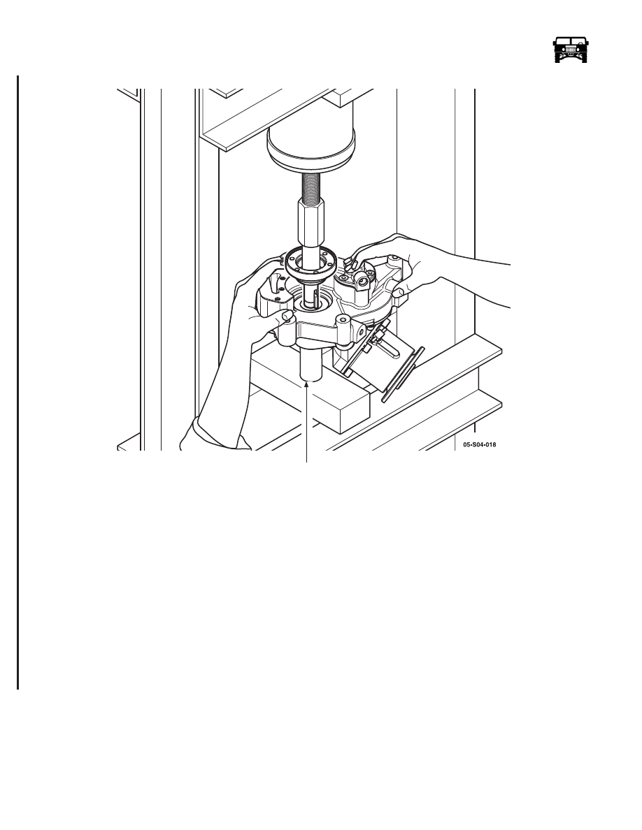
Press the input shaft into the GFD (Figure 4-37).
Figure 4-37: Pressing The Input Shaft
8.
Install tool J-8814-11 onto the output flange, apply medium strength thread locker and torque the output shaft nut to 110 lb. ft.
(150 N•m) (Figure 4-30).
9.
With tool J-8814-11 still installed and using tool EN-48032, torque the input shaft nut to 70 lb. ft. (95 N•m) if the lock-washer
tab does not line up, continue to tighten until tab alignment can be achieved. Once alignment is achieved, bend the lock tab in
place to secure the nut.
10. Apply aviation gasket sealant to the sealing surface and install the core plug (Figure 4-31).
11. Apply a thin coat of gear lube on the gerotor pump and install it onto the transfer shaft (Figure 4-28).
12. Install new o-rings on the pump housing, install the relief spring and ball in the rear case, install the pump housing to the rear
case and torque to 9 lb. ft. (12 N•m) (Figure 4-28).
13. Install the sump assembly with a new gasket and torque the bolts to 18.5 lb. ft. (25 N•m).
14. Install the oil pipe and torque the nuts to 19 lb. ft. (26 N•m) (Figure 4-27).
15. Install the GFD and fill with fluid.
BEARING SUPPORT
12-1-05