Hummer H1 (2006+). Manual - part 178
 

  Index      Hummer     Hummer H1 DMAX - service repair manual 2006 year


Search            


Content   ..  176  177  178  179   ..


Hummer H1 (2006+). Manual - part 178


3-54 Fuel, Emissions, and Exhaust

___________________________________________

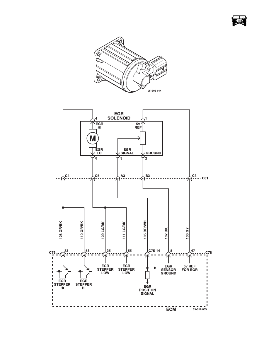
Figure 3-36:   EGR Valve

Figure 3-37:   EGR Valve Electrical Circuit

___________________________________________

 Fuel, Emissions, and Exhaust  3-55

EGR Cooler

The EGR cooler, located next to the right side intake manifold, has engine coolant circulating through it to cool the exhaust charge
before it enters the intake manifold (Figure 3-38).

Figure 3-38:   EGR Cooler

Removal

1.

Disconnect negative battery cable.

2.

Drain the cooling system (Refer to section 4)

3.

Remove the air induction hose (Refer to section 3).

4.

Loosen the charged air cooler outlet duct to intake hose clamp.

5.

Remove the charged air cooler outlet duct from the intake.

6.

Remove the right side positive crankcase ventilation (PCV) hose/pipe.

7.

Remove the air inlet tube to intake manifold tube bolt and nut (Figure 3-39).

8.

Remove the air inlet tube nuts (Figure 3-40).

9.

Remove the air inlet tube.

10. Disconnect the exhaust gas recirculation (EGR) valve electrical connector.

11. Disconnect the EGR cooler heater hose.

12. Remove the EGR coolant pipe bolts.

13. Remove the EGR coolant pipe.

14. Remove the EGR cooler bolts (Figures 3-41 and 3-42).

15. Remove the EGR cooler.

EGR COOLER

3-56 Fuel, Emissions, and Exhaust

___________________________________________

Figure 3-39:   Intake Manifold Tube Bolt and Nut

Figure 3-40:   Air Inlet Tube Nuts

NUT

BOLT

INTAKE TUBE

INTAKE TUBE

NUTS

___________________________________________

 Fuel, Emissions, and Exhaust  3-57

Figure 3-41:   EGR Cooler Upper Bolts

Figure 3-42:   EGR Cooler Rear Bolts

Installation

1.

Install the EGR cooler and torque the rear bolts to 15 lb-ft. (20 N·m)  (See Figure 3-42) and the upper bolts to 37 lb-ft. 
(50 N·m) (See Figure 3-41).

2.

Install the EGR coolant pipe and torque the bolts to 18 lb-ft. (25 N·m).

3.

Connect the EGR cooler heater hose.

4.

Connect the EGR valve electrical connector.

5.

Install the air inlet tube.

6.

Install the air inlet tube nuts and torque to 18 lb-ft. (25 N·m).

7.

Install the air inlet tube to intake manifold tube bolt and nut and torque to 89 lb-in. (10 N·m).

8.

Install the right side PCV hose/pipe.

9.

Install the air induction hose and torque the clamps to 35 lb-in. (4 N·m)

10. Fill and bleed the cooling system.

11. Connect the negative battery cable.

EGR COOLER 

BOLT

EGR COOLER

BOLTS


Content   ..  176  177  178  179   ..