Hummer H1 (2006+). Manual - part 91
 

  Index      Hummer     Hummer H1 DMAX - service repair manual 2006 year


Search            


Content   ..  89  90  91  92   ..


Hummer H1 (2006+). Manual - part 91


OBD-208

On-Board Diagnostics

_____________________________________________

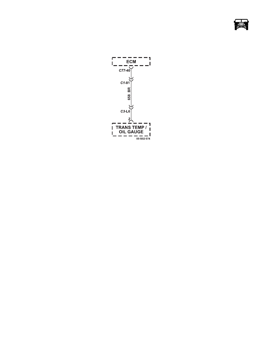
DTC P0650 Malfunction Indicator Lamp (MIL) Control Circuit (Figure OBD-58)

Figure OBD-58:   Malfunction Indicator Lamp (MIL) Control Circuit

Circuit Description

The malfunction indicator lamp (MIL) is located on the instrument panel cluster (IPC). The MIL informs the driver that an emis-
sion system fault has occurred and that the engine control system requires service. The control module monitors the MIL control
circuit for conditions that are incorrect for the commanded state of the MIL. For example, a failure condition exists if the control
module detects low voltage when the MIL is commanded OFF, or high voltage when the MIL is commanded ON. If the control
module detects an improper voltage on the MIL control circuit, DTC P0650 will set.

Conditions for Setting the DTC 

• The control module detects that the commanded state of the MIL driver and the actual state of the control circuit do not 

match.

• The conditions are present for a minimum of 30 seconds. 

Action Taken When the DTC Sets 

• The control module illuminates the malfunction indicator lamp (MIL) when the diagnostic runs and fails. 

• The control module records the operating conditions at the time the diagnostic fails. The control module stores this informa-

tion in the Freeze Frame/Failure Records. 

Conditions for Clearing the MIL/DTC 

• The control module turns OFF the malfunction indicator lamp (MIL) after 3 consecutive ignition cycles that the diagnostic 

runs and does not fail. 

• A current DTC, Last Test Failed, clears when the diagnostic runs and passes. 

• A history DTC clears after 40 consecutive warm-up cycles, if no failures are reported by this or any other emission related 

diagnostic.

• Clear the MIL and the DTC with a scan tool.

_____________________________________________

 On-Board Diagnostics  OBD-209

5745804

Step

Action

Value(s)

Yes

No

    1

NOTE: Before clearing DTC(s) use the scan tool “Capture info”
to record Freeze Frame and Failure Records for reference, as data
will be lost when “Clear Info” function is used 

Was the “On-Board Diagnostic (OBD) System Check” per-
formed?

Go to step 2.

Go to OBD Sys-

tem Check.

    2

1.

Verify whether the instrument cluster is operational.

2.

Command the MIL ON and OFF with a scan tool. 

Does the malfunction indicator lamp (MIL) turn ON and OFF
when commanded with a scan tool?

Go to Step 3

Go to Step 4

    3

1.

Observe the Freeze Frame/Failure Records for this DTC.

2.

Turn OFF the ignition for 30 seconds.

3.

Start the engine.

4.

Operate the vehicle within the Conditions for Running the 
DTC. You may also operate the vehicle within the conditions 
that you observed from the Freeze Frame/Failure Records.

Does the DTC fail this ignition?

Go to Step 4

Go to Intermit-

tent Conditions

    4

Turn OFF the ignition.

5.

Disconnect the engine control module (ECM). 

6.

Turn ON the ignition, with the engine OFF.

Is the MIL OFF?

Go to Step 5

Go to Step 10 

    5

1.

Remove fuse 4B that supplies voltage to the instrument panel 
cluster (IPC).

2.

Measure the voltage from the MIL control circuit 658 (BR) 
in the ECM harness C77 pin 40 to a good ground.

Is the voltage less than the specified value?

1 Volt

Go to Step 6 

Go to Step 11

    6

1.

Turn OFF the ignition.

2.

Install the fuse that supplies ignition voltage to the MIL.

3.

Turn ON the ignition, with the engine OFF.

4.

Connect a 3-amp fused jumper wire between the MIL control 
circuit 658 (BR) of the ECM harness connector and a good 
ground.

Is the MIL illuminated?

Go to Step 9 

Go to Step 7

    7

Test the MIL control circuit 658 (BR) for an open or high resis-
tance between C77 pin 40 and pin 2 of the trans temp/oil gauge.

Did you find and correct a condition?

Go to Step 14 

Go to Step 8 

    8

Test for an intermittent and for a poor connection at the IPC.

Did you find and correct the condition?

Go to Step 14 

Go to Step 12

    9

Test for an intermittent and for a poor connection at the ECM. 

Did you find and correct the condition?

Go to Step 14

Go to Step 13

    10

Test for a short to ground in the MIL control circuit 658 (BR) be-
tween C77 pin 40 and pin 2 of the trans temp/oil gauge. 

Did you find and correct the condition?

Go to Step 14

Go to Step 12 

OBD-210

On-Board Diagnostics

_____________________________________________

    11

Repair the short to voltage in the MIL control circuit 658 (BR)
between C77 pin 40 and pin 2 of the trans temp/oil gauge. 

Did you complete the repair?

Go to Step 14 

    12

Replace the faulty IPC. 

Did you complete the replacement?

Go to Step 14 

    13

Replace the faulty ECM. 

Did you complete the replacement?

Go to Step 14 

    14

1.

Clear the DTCs with a scan tool.

2.

Turn OFF the ignition for 30 seconds.

3.

Start the engine.

4.

Operate the vehicle within the Conditions for Running the 
DTC. You may also operate the vehicle within the conditions 
that you observed from the Freeze Frame/Failure Records.

Did the DTC fail this ignition?

Go to Step 1 

Go to Step 5

   15

Using the Scan Tool select “Capture Info,” Review Info.” Are
any DTC’s displayed that have not been diagnosed?

Go to the appli-

cable DTC 

table.

System OK.

Step

Action

Value(s)

Yes

No

_____________________________________________

 On-Board Diagnostics  OBD-211

5745804

DTC P0652 5 Volt Reference 2 Circuit Low Voltage (Figure OBD-59)

Figure OBD-59:   5 Volt Reference 2 Circuit

Circuit Description

The engine control module (ECM) provides 5 volts to the following sensors:

• The boost sensor 

• The accelerator pedal position (APP) 2 sensor 

• The turbocharger vane position sensor 

• The A/C refrigerant pressure sensor 

• The barometric pressure (BARO) sensor 

These 5-volt reference circuits are independent of each other outside the ECM, but are bussed together inside the ECM. Therefore,
a circuit condition on one sensor 5-volt reference circuit may affect the other sensor 5-volt reference circuits. The ECM monitors
the voltage on the 5-volt reference circuit. If the ECM detects a low voltage condition, DTC P0652 sets.

Conditions for Setting the DTC 

• The ECM detects the 5-volt reference circuit 2 voltage is less than 4.7 volts. 

• The above condition is present for 2 seconds. 

Action Taken When the DTC Sets 

• *The control module illuminates the malfunction indicator lamp (MIL) when the diagnostic runs and fails. 

• *The control module records the operating conditions at the time the diagnostic fails. The control module stores this infor-

mation in the Freeze Frame/Failure Records. 


Content   ..  89  90  91  92   ..