Hummer H1 (2002+). Manual - part 276
_____________________________________________________
PCM/Tech 1 Scan Tool 37
®
05745159
DTC P0123 Accelerator Pedal Position (APP)
Sensor 1 Circuit High Voltage
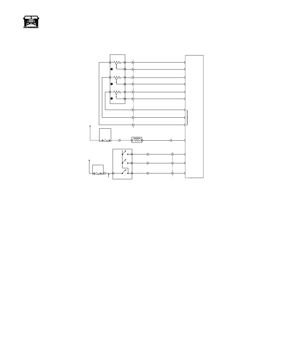
Circuit Description
The Accelerator Pedal Position (APP) module provides a volt-
age signal that changes relative to accelerator position. There
are three sensors located within the APP module that are scaled
differently. This is a type C DTC.
Conditions for Setting the DTC
• Voltage is greater than 4.75 volts on APP 1 sensor.
• Conditions met for 2 seconds.
Action Taken When the DTC Sets
• The input from APP 1 sensor is ignored.
• A current and history DTC will set but it will not turn on
the “Check Throttle” lamp. The throttle will operate
normally as long as there is only one sensor malfunc-
tioning. If two different APP sensors have a malfunc-
tion, the “Check Throttle” lamp will light and the PCM
will limit power. If three APP sensors have a malfunc-
tion present, the “Service Throttle Soon” lamp will light
and the PCM will only allow the engine to operate at
idle.
Conditions for Clearing the MIL/DTC
• A History DTC will clear when forty consecutive
warm-up cycles that the diagnostic does not fail (coolant
temperature has risen 5°C (40°F) from start up coolant
temperature and engine coolant temperature exceeds
71°C (160°F) that same ignition cycle).
• Use of a Scan Tool
Diagnostic Aids
A scan tool reads APP 1 position in volts. It should read about
.45 to .95 volt with throttle closed and ignition “ON” or at idle.
Voltage should increase at a steady rate as throttle is moved to-
ward Wide Open Throttle (WOT). Also, 90% pedal travel is
acceptable for correct APP operation. Scan APP 1 sensor while
depressing accelerator pedal with engine stopped and ignition
“ON”. Display should vary from about .74 volt when throttle is
closed to about 3.7 volts when throttle is held at Wide Open
Throttle (WOT) position. A P0123 will result if the ground cir-
cuit is open or the signal circuit is shorted to voltage. Refer to
Intermittents in Section 2.
Test Description
Number(s) below refer to the number(s) on the diagnostic ta-
ble.
2. This step determines if DTC P0123 is the result of a hard
failure or an intermittent condition.
3. This step checks the PCM and wiring.
FUSE 5C
10AMP
INTERIOR
FUSE 3A
10 AMP
EXTERIOR
ON/
OFF
SET
COAST
RESUME
ACCEL
HOT IN RUN
AND START
HOT IN RUN
AND START
A
29
42
37
C1
C29-A11
C29-B11
C27-D10
C28-D14
C28-C2
C27-D12
C27-D3
C27-D4
C27-D6
C29-B2
C29-B1
C27-C5
C29-A12
C5-D3
C5-A4
A
B
154 TN
151 GY
152 DB
153 LG
ON / OFF
SIGNAL
SET
COAST
SIGNAL
RESUME
ACCEL
SIGNAL
WASTEGATE
SOLENOID
CONTROL
5 VOLT
REFERENCE
APP 3
SIGNAL
GROUND
APP 1
SIGNAL
GROUND
GROUND
D
B
C
A
G
E
F
J
K
3
1
2
C1
22
20
14
15
60
32
53
17
44
720 TN
717 WH
723 YL
724 DG
725 GY
718 DB
719 BR
721 LB
722 PP
ACCELERATIOR
PEDAL POSITION
SENSOR
POWERTRAIN
CONTROL
MODULE
(PCM)
APP 2
SIGNAL
9-S12-055
B
C
D
295 BR
YL
GRN
RD