Hummer H1 (2002+). Manual - part 273


  Index      Hummer     Hummer H1 - service repair manual 2002 year


Search            


Content   ..  271  272  273  274   ..


Hummer H1 (2002+). Manual - part 273


_____________________________________________________

PCM/Tech 1 Scan Tool 25

®

05745159

DTC P0112 Intake Air Temperature (IAT) 
Sensor Circuit Low Voltage

Circuit Description

The Intake Air Temperature (IAT) sensor is a thermistor that
controls signal voltage to the PCM. When the air is cold, the
sensor resistance is high, therefore the PCM will see a high sig-
nal voltage. As air warms, sensor resistance becomes less and
voltage drops.

Conditions for Setting the DTC

• Engine coolant temperature less than 42.5°C (109°F).

• Intake air temperature greater than or equal to 151°C 

(303°F).

• Conditions met for 2 seconds.

Action Taken When the DTC Sets

A possible poor performance problem may exist during cold
weather operation.

Conditions for Clearing the MIL/DTC

• The PCM will turn the MIL off after three consecutive 

trips without a fault condition.

• A History DTC will clear when forty consecutive 

warm-up cycles that the diagnostic does not fail (coolant 
temperature has risen 5°C (40°F) from start up coolant 
temperature and engine coolant temperature exceeds 
160°F (71°C) that same ignition cycle).

• Use of a Scan Tool

Diagnostic Aids

Check harness routing for a potential short to ground in the sig-
nal circuit. Scan Tool displays intake air temperature in de-
grees centigrade. Refer to “Intermittents” on page 13. A
“skewed” sensor could result in poor driveability complaints.

Test Description

Number(s) below refer to the step number(s) on the Diagnostic
Table.

3. This step determines if P0112 is a hard failure or an intermit-

tent condition.

4. This test will determine if the PCM can recognize an open

sensor.

5. This step will determine if the problem is a short to ground

or a malfunctioning PCM.
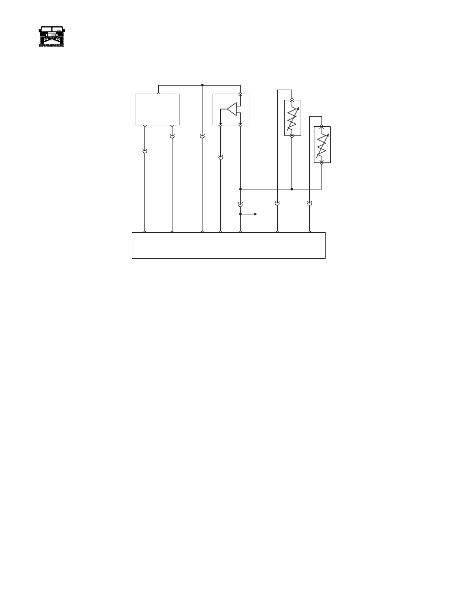
5 VOLT

REFERNCE

CKP
SENSOR
SIGNAL

SENSOR

GROUND

CRANK
SHAFT
POSITION
SENSOR
(CKP)

A

B

B

A

B

B

A

A

C

C

C5-B12

C5-B5

C5-B9

BOOST/
BARO
PRESSURE
SENSOR

INTAKE AIR
TEMPERATURE
SENSOR (IAT)

ENGINE
COOLANT
TEMP
SENSOR
(ECT)

C5-B10

POWERTRAIN
CONTROL
MODULE

CKP

SENSOR

SIGNAL

SENSOR

GROUND

5 VOLT

REFERENCE

BOOST

SENSOR

SIGNAL

SENSOR

GROUND

ECT

SENSOR

SIGNAL

IAT

SENSOR

SIGNAL

C29-A5

359 BK

C5-C4

C5-C5

C27-C1

C27-D13

C27-C14

C29-B12

349 YL

651 PP

350 LG

394 LB

359 BK

C5-B11

TO
TFT
SENSOR

357 TN

354 YL

9-S12-066

26

PCM/Tech 1 Scan Tool

_____________________________________________________

®

DTC P0112 - Intake Air Temperature (IAT) Sensor Circuit Low Voltage

Step

Action

Value(s)

Yes

No

1

NOTE:

 Before clearing DTC(s) use the Scan tool “Capture Info” to

record Freeze Frame and Failure Record for reference, as data will
be lost when “Clear Info” function is used.

Was the “On-Board Diagnostic (OBD) System Check” performed?

Go to Step 2 Go to OBD 

System Check

2

1. Scan tool connected.
2. Start the engine.

3. Monitor the IAT display on Scan Tool.

Is the IAT display greater than or equal to the specified value?

151°C

(303°F)

Go to Step 3 Go to Step 5

3

1. Turn the engine “OFF.”
2. Turn the ignition “ON.”

3. Disconnect the IAT sensor connector.

Is the IAT display less than or equal to the specified value?

-30°C

(-22°F)

Go to Step 7 Go to Step 4

4

1. Turn the ignition “OFF”.
2. Using the J–39200, measure the resistance across the IAT sensor har-

ness connector.

Is the resistance at the specified value?

Infinite

Go to Step 8 Go to Step 6

5

DCT is intermittent. If no additional DTCs are stored, refer to “Diagnostic 
Aids.” If additional DTCs were stored, refer to those table(s).
Are additional DTCs stored?

Go to the 

applicable 

DTC Table

Go to 

Diagnostic 

Aids

6

Repair the short to ground in the IAT signal circuit.
Is the action complete?

Go to Step 9

7

Replace the IAT sensor.
Is the action complete?

Go to Step 9

8

Replace the faulty PCM. 

NOTE: If the PCM is faulty, the new PCM must be programmed.
Go to PCM replacement and programming procedures.

Is the action complete?

Go to Step 9

9

1. Using the Scan Tool, select “DTC,” “Clear Info.”
2. Start engine and idle at normal operating temperature.

3. Select “DTC,” “Specific,” then enter the DTC number which was set.

4. Operate vehicle within the conditions for setting this DTC as specified

in the supporting text.

Does the Scan Tool indicate that this diagnostic Ran and Passed?

Go to Step 

10

Go to Step 2

10

Using the Scan Tool, select “Capture Info,” “Review Info.”
Are any DTC’s displayed that have not been diagnosed?

Go to the 

applicable 

DTC table

System OK

_____________________________________________________

PCM/Tech 1 Scan Tool 27

®

05745159

DTC P0113 Intake Air Temperature (IAT) 
Sensor Circuit High Voltage

Circuit Description

The intake air temperature sensor is a thermistor that controls
signal voltage to the PCM. When the air is cold, the sensor re-
sistance is high, therefore the PCM will see a high signal volt-
age. As air warms, sensor resistance becomes less and voltage
drops. This is a type B DTC.

Conditions for Setting the DTC

• Engine operating for 8 minutes.

• IAT less than or equal to -30°C (-22°F).

• Conditions met for 2 seconds.

Action Taken When the DTC Sets

Possible poor performance during cold weather operation.

Conditions for Clearing the MIL/DTC

• The PCM will turn the MIL off after three consecutive 

trips without a fault condition.

• A History DTC will clear when forty consecutive 

warm-up cycles that the diagnostic does not fail (Cool-
ant temperature has risen 5°C(40°F) from start up cool-
ant temperature and engine coolant temperature exceeds 
160°F (71°C) that same ignition cycle).

• Use of a scan tool.

Diagnostic Aids

The scan tool displays intake air temperature in degrees centi-
grade. Refer to “Intermittent” on page 13. A “skewed” sensor
could result in poor driveability complaints.

Test Description

Number(s) below refer to the step number(s) on the diagnostic
Table.

5. This step determines if P0113 is a hard failure or an intermit-

tent condition.

6. This step will determine if there is a wiring problem or

a faulty PCM.

5 VOLT

REFERNCE

CKP
SENSOR
SIGNAL

SENSOR

GROUND

CRANK
SHAFT
POSITION
SENSOR
(CKP)

A

B

B

A

B

B

A

A

C

C

C5-B12

C5-B5

C5-B9

BOOST/
BARO
PRESSURE
SENSOR

INTAKE AIR
TEMPERATURE
SENSOR (IAT)

ENGINE
COOLANT
TEMP
SENSOR
(ECT)

C5-B10

POWERTRAIN
CONTROL
MODULE

CKP

SENSOR

SIGNAL

SENSOR

GROUND

5 VOLT

REFERENCE

BOOST

SENSOR

SIGNAL

SENSOR

GROUND

ECT

SENSOR

SIGNAL

IAT

SENSOR

SIGNAL

C29-A5

359 BK

C5-C4

C5-C5

C27-C1

C27-D13

C27-C14

C29-B12

349 YL

651 PP

350 LG

394 LB

359 BK

C5-B11

TO
TFT
SENSOR

357 TN

354 YL

9-S12-066

28

PCM/Tech 1 Scan Tool

_____________________________________________________

®

DTC P0113 - Intake Air Temperature (IAT) Sensor Circuit High Voltage

Step

Action

Value(s)

Yes

No

1

NOTE:

 Before clearing DTC(s) use the Scan tool “Capture Info” to record

Freeze Frame and Failure Record for reference, as data will be lost when
“Clear Info” function is used.

Was the “On-Board Diagnostic (OBD) System Check” performed?

Go to Step 2

Go to OBD 

System 

Check

2

1. Scan tool connected.
2. Start the engine.

3. Monitor the IAT display on Scan Tool.

Is the IAT display colder than or equal to the specified value?

-30°C

(-22°F)

Go to Step 3

Go to Step 5

3

1. Turn the engine “OFF.”
2. Turn the ignition “ON.”

3. Disconnect the IAT sensor connector.

4. Jumper the IAT harness terminals together.

Does the scan tool display IAT greater than or equal to the specified
value?

151°C

(303°F)

Go to Step 6

Go to Step 4

4

Jumper the IAT sensor signal circuit to a known good ground.
Does the scan tool display an IAT greater than or equal to the specified
value?

151°C

(303°F)

Go to Step 7

Go to Step 8

5

DTC is intermittent. If no additional DTCs are stored, refer to “Diagnostic 
Aids.” 
Are additional DTCs stored?

Go to the 

applicable 

DTC Table

Go to 

Diagnostic 

Aids

6

Inspect the sensor connector and PCM connector for a proper connection.
Was a problem found?

Go to Step 9

Go to Step 10

7

Check the IAT sensor ground circuit for an open between the IAT sensor 
and the PCM.
Was a problem found?

Go to Step 9

Go to Step 11

8

Check the IAT sensor signal circuit for an open between the IAT sensor
and the PCM.
Was a problem found?

Go to Step 9

Go to Step 11

9

Repair the circuit as necessary.
Is the action complete?

Go to Step 12

10

Replace the faulty IAT sensor.
Is the action complete?

Go to Step 12

11

Replace the faulty PCM.

NOTE:

 If the PCM is faulty, the new PCM must be programmed. Go to

PCM replacement and programming procedures.

Is the action complete?

Go to Step 12

12

1. Using the Scan Tool, select “DTC,” “Clear Info.”
2. Start engine and idle at normal operating temperature.

3. Select “DTC,” “Specific,” then enter the DTC number which was set.

4. Operate vehicle within the conditions for setting this DTC as specified

in the supporting text.

Does the Scan Tool indicate that this diagnostic Ran and Passed?

Go to Step 13

13

Using the Scan Tool, select “Capture Info,” “Review Info.”
Are any DTC’s displayed that have not been diagnosed?

Go to the 

applicable 

DTC table

System OK


Content   ..  271  272  273  274   ..