Hummer H1 (2002+). Manual - part 210


  Index      Hummer     Hummer H1 - service repair manual 2002 year


Search            


Content   ..  208  209  210  211   ..


Hummer H1 (2002+). Manual - part 210


______________________________________________________

 Electrical System  12-67

®

05745159

Speedometer/Odometer Replacement

Removal 

1.

Remove the left A-pillar dash trim (closeout).

2.

Remove the left footwell closeout panel and disconnect
the courtesy light plug, diagnostic link connector and the
footwell vent hose from the closeout panel.

3.

If equipped with power mirrors, pop the switch from dash
and let hang to gain access to the crossbolt nut.

4.

Remove the two screws securing the harness hanger to the
steering column mount bracket and remove the harness
hanger.

5.

Loosen the two bolts at the forward steering column pivot
point.

6.

Remove the steering column crossbolt, nut and washer and
tilt the steering column downward.

7.

Remove two trim screws from the crashpad and pull
rearward to release the crashpad.

8.

Remove the two speedometer/odometer hold-down
bracket nuts and lockwashers and the hold-down bracket.

9.

Pull the speedometer/odometer from the dash Remove the
wire connector from the backside of the speedometer.

Installation 

1.

Insert speedometer/odometer into instrument panel  
(Figure 2-89).

2.

Install the crashpad using two trim screws.

3.

Install the left and right gauge bezels.

4.

Tilt the steering column up and install the crossbolt, nut
and washer.

5.

Tighten the two bolts at the forward pivot point of the
steering column. 

6.

Screw the harness hanger to the steering column mount
bracket.

7.

Install the power mirror switch if removed in step 3 above.

8.

Install the footwell vent hose, the DLC, the courtesy light
plug and the left footwell closeout panel.

9.

Install the left A-pillar dash trim (closeout). 

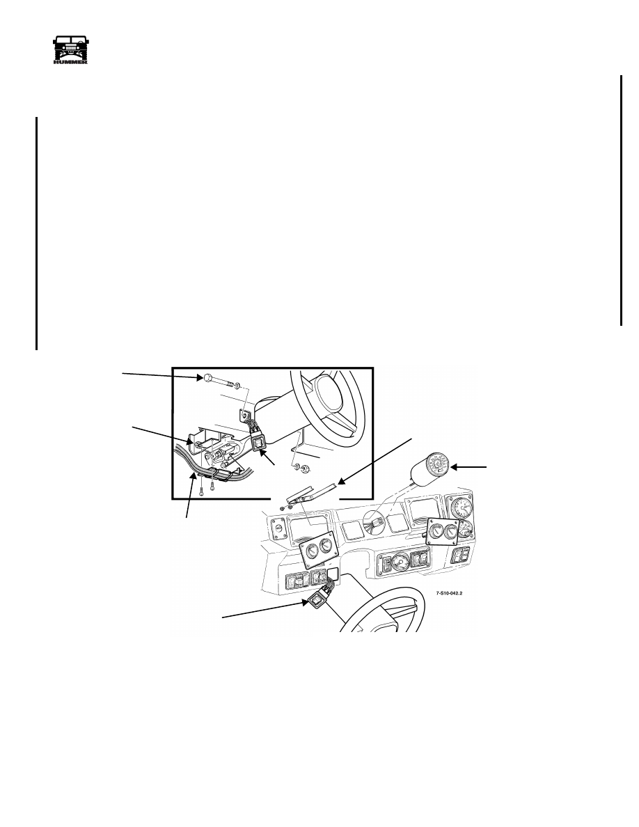
Figure 2-89:   Speedometer/Odometer Replacement

HOLD-DOWN

PIVOT BOLT

POWER

CROSSBOLT

HARNESS

SPEEDOMETER/

HANGER

BRACKET

ODOMETER

MIRROR
SWITCH

POWER
MIRROR
SWITCH

3-1-01

12-68

Electrical System

_______________________________________________________

®

Tachometer Replacement

NOTE: Mark position of set screws in relationship to tachom-
eter clock panel before disassembly. Tachometer mounting
clamp must be installed in factory position to have proper
clearance for reassembly.

NOTE: It may be necessary to remove clock for access to ta-
chometer mounting clamp hardware.

Removal

1.

Remove screws and tachometer/clock panel from I.P.

2.

Unplug tachometer electrical connector from I.P. wiring
harness.

3.

Loosen set screws and tachometer mounting clamp
hardware. Remove clamp from tachometer housing.

4.

Remove tachometer from tachometer/clock panel.

Installation

1.

Position tachometer in tachometer/clock panel.

2.

Slide tachometer mounting clamp onto tachometer
housing; close enough to tachometer/clock panel for set
screws to make contact.

3.

Tighten clamp securely onto tachometer body and tighten
setscrews until they contact tachometer/clock panel.

4.

Plug tachometer electrical connector into I.P. wiring
harness.

5.

Secure tachometer/clock panel to I.P. with screws.

Figure 2-90:   Tachometer Mounting

CIGARETTE LIGHTER REPLACEMENT

Removal 

1.

Pull front console away from dashpad enough to gain 
access to wiring harness connector.

2.

Remove wiring harness connector from lighter assembly.

3.

Remove element from lighter assembly heater (Figure 2-91).

4.

Remove shell from heater, and remove shell, heater, and
bezel from console.

Installation 

1.

Install bezel and heater in console (Figure 2-91).

2.

Install shell on heater.

3.

Install wiring harness connector on lighter assembly.

4.

Install element in lighter assembly.

5.

Engage cigarette lighter to ensure proper operation.

6.

Install front console.

Figure 2-91:   Cigarette Lighter Breakdown

PASS

ED

PASSED

P

A

S

S

E

D

6-S10-018.1

TACHOMETER

MOUNTING

CLAMP

TACHOMETER

MOUNTING

CLAMP

HARDWARE

SET SCREW

CLOCK MOUNTING

CLAMP

CLOCK

TACHOMETER

TACHOMETER/CLOCK

PANEL

WIRING HARNESS

SHELL

ELEMENT

HEATER

CONSOLE

 CONNECTOR

LIGHTER 

ASSEMBLY

BEZEL

4-1-00

______________________________________________________

 Electrical System  12-69

®

05745159

LOW COOLANT LAMP INOPERATIVE

The coolant level sensor is a solid-state semi-conductor device.
The sensor’s resistance varies as a function of its temperature.
As voltage/current flows through the sensor, sensor tempera-
ture increases. In the presence of a liquid, in this case engine
coolant, the temperature of the sensor is controlled by transfer-
ring heat to the coolant. Should the coolant level drop below
the sensor, the heat and resistance of the sensor will rise. The
“Low Coolant” warning light will then illuminate in response
to the increased resistance at the sensor. 


Step

Action

Value(s)

Yes

No

1

Disconnect connector C35 from low coolant sen-
sor pigtail. Turn ignition switch to ON. Check ter-
minal A (pink wire) for voltage. Is voltage 
present?

Approximate 

battery voltage.

Go to step 2.

Repair circuit 
291 from fuse 
3B in exterior 
fuse box.

2

Disconnect connector C35 from low coolant sen-
sor pigtail. Turn ignition switch to ON. Connect a 
fused jumper from terminal A (pink wire) to ter-
minal B (red wire) of the harness side of connec-
tor C35.
Does the low coolant lamp light?

Go to step 3.

Check/repair 
signal circuit 
794 and lamp in 
status center.

3

Check/repair circuit 57 (black wire) from sensor 
to engine ground.
Does the low coolant lamp light?

Repair complete.

Repair connec-
tion at connec-
tor C35 or 
replace sensor

4-1-00

12-70

Electrical System

_______________________________________________________

®

Figure 2-92:   Low Coolant Sensor Schematic

LOW COOLANT SENSOR

291 PNK

794 RED

57 BLK

FUSE 3B

20 AMP

EXTERIOR

794 RED

G1

RIGHT STATUS CENTER

LOW COOLANT

LAMP

C1-55

C9   J

C4   3

11

G3

IGNITION

A

B

C

C3   N7

G

C35

9-S12-092

FUSE 4B
5 AMP
INTERIOR
FUSE BOX

30 GY

IGNITION

4-1-00


Content   ..  208  209  210  211   ..