Hummer H1 (2002+). Manual - part 202
______________________________________________________
Electrical System 12-35
®
05745159
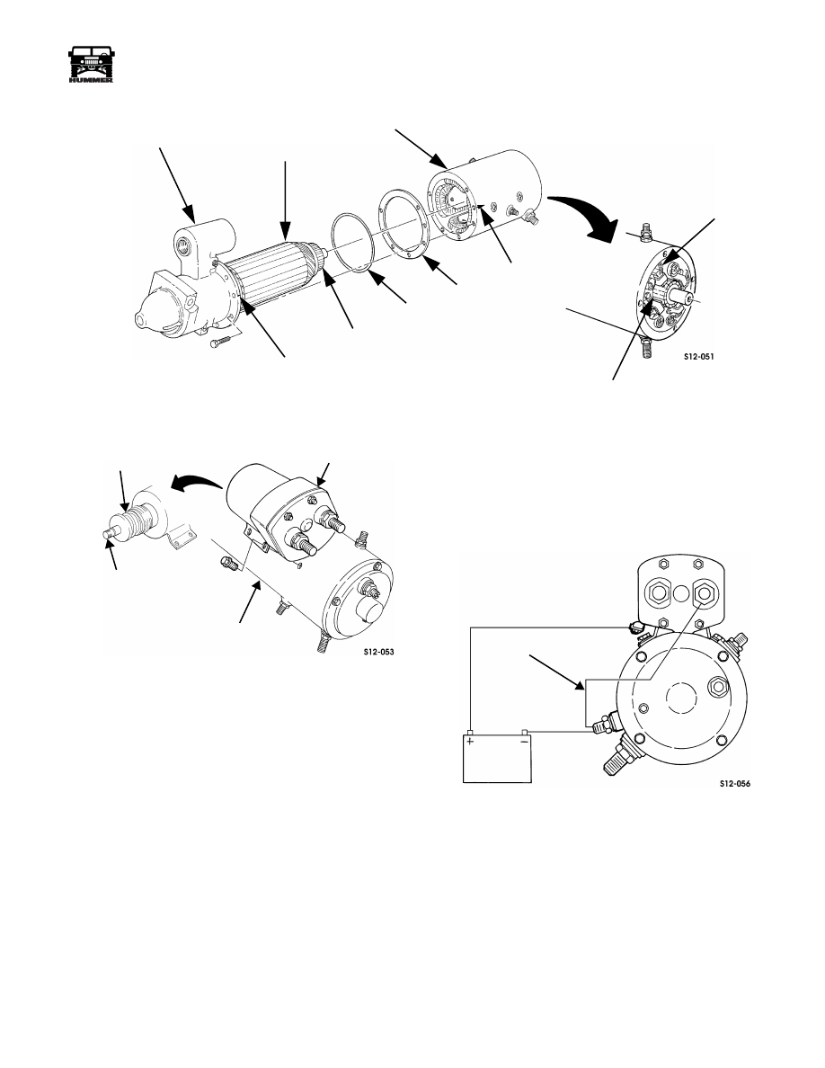
Figure 12-66: Assembling Frame, Armature, and Pinion Housing
Figure 12-67: Solenoid Boot Installation
Starter Pinion Clearance
Adjustment
1.
Connect battery and jumper to starter as shown
(Figure 12-68). Momentarily touch jumper to solenoid
frame to shift pinion into cranking position.
Figure 12-68: Battery and Jumper Connections
for Pinion Clearance Check
2.
Check clearance between pinion and snap ring with feeler
gauge (Figure 12-69).
3.
Disconnect battery.
4.
Pinion clearance should be 0.005-0.030 in. (0.127-0.762
mm). If adjustment is necessary, remove end plate and add
or remove thrust washer(s) (Figure 12-69).
PINION HOUSING
ARMATURE
FRAME
MARK
GASKET
O-RING
COMMUTATOR
COMMUTATOR
BRUSHES
SCRIBE
MARK
SCRIBE
SOLENOID
FRAME
BOOT (COAT
CORE SHAFT
WITH GREASE)
JUMPER WIRE
4-1-00