Hummer H1 (2002+). Manual - part 144
________________________________________
Axles, Suspension, and Frame 9-37
®
05745159
33. Install differential assembly, bearing cups, and shims in
housing.
34. Install two bearing caps and four bolts in housing. Snug
bolts.
35. Mount dial indicator on housing and position indicator to
read off ring gear mounting surface of differential
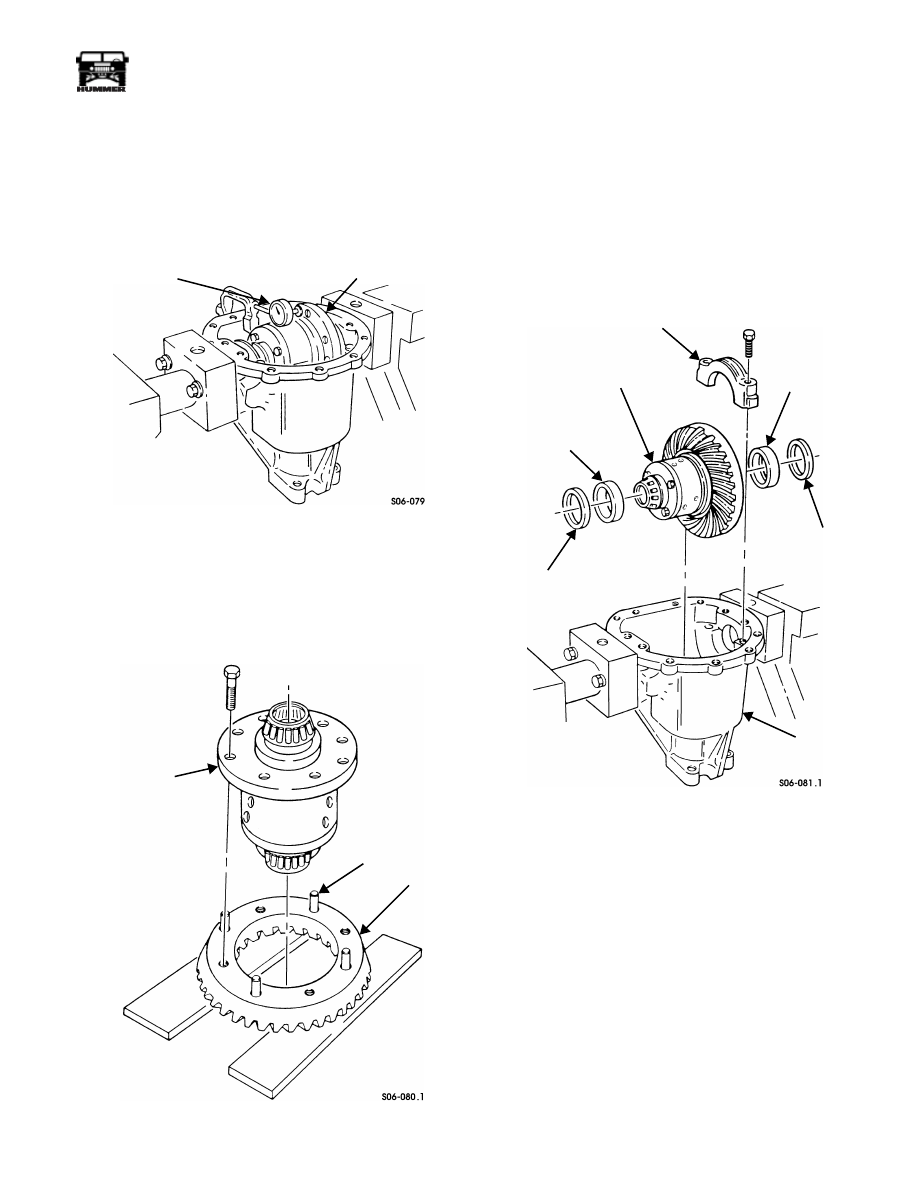
assembly (Figure 9-94).
Figure 9-94: Dial Indicator Positioning For Case
Runout Check
36. Pry between differential assembly and bearing cap on one
side of indicator. Pry on opposite side to read end play.
37. Amount read on indicator is shim thickness that should be
added to side bearing shims to arrive at zero end play. Add
necessary shims and repeat procedure to ensure accuracy.
Figure 9-95: Ring Gear Guide Pin Installation
38. Tighten four bolts to 55-70 lb-ft (75-95 N•m).
39. Rotate differential assembly and check runout. Runout
should not exceed 0.002 in. (0.05 mm).
40. Remove dial indicator from housing.
NOTE:
Tag shims and bearing cups for assembly.
41. Remove four bolts, two bearing caps, bearing cups, shims,
and differential assembly from housing (Figure 9-96).
42. Install four guide pins in ring gear (Figure 9-95).
Figure 9-96: Differential Assembly Mounting
43. Support ring gear with wood blocks in press.
44. Press differential assembly on ring gear.
45. Remove four guide pins from ring gear.
46. Install ring gear on differential assembly with eight bolts.
Tighten bolts to 95-115 lb-ft (129-156 N•m).
47. Install side bearing shims, previously selected to remove
differential assembly side play, slide bearing cups, and
differential assembly in housing (Figure 9-96).
48. Install two bearing caps in housing with four bolts.
Tighten bolts to 55-70 lb-ft (75-95 N•m).
49. Attach dial indicator to housing and position indicator to
read off drive side of ring gear tooth at a right angle
(Figure 9-97).
RING GEAR
FLANGE OF CASE
DIAL INDICATOR
DIFFERENTIAL
CASE
RING GEAR
GUIDE PIN
BEARING
BEARING
DIFFERENTIAL
BEARING
BEARING
BEARING SHIM
HOUSING
CUP
SHIM
CAP
ASSEMBLY
CUP