Hummer H1 (2002+). Manual - part 136


  Index      Hummer     Hummer H1 - service repair manual 2002 year


Search            


Content   ..  134  135  136  137   ..


Hummer H1 (2002+). Manual - part 136


__________________________________________


 Axles, Suspension, and Frame  9-5


®


05745159


LOWER BALL JOINT REPLACEMENT


Removal 


1.

Remove wheel.

2.

Raise and support lower control arm (Figure 9-8).

3.

Remove cotter pin and slotted nut from lower ball joint.
Discard cotter pin.

4.

Remove four locknuts, bolts, eight washers and lower ball
joint from lower control arm.

5.

Separate lower ball joint from geared hub using ball joint
remover J–24319-B or equivalent. Remove lower ball
joint.


Installation 


1.

Install lower ball joint on lower control arm, ensuring low-
er ball joint is placed below lower control arm and secure 
with four bolts, locknuts and eight washers. Tighten  7/16” 
locknuts to 65 lb-ft (80 N•m) (Figure 9-8).


CAUTION: 


Do not loosen slotted nut to install cotter pin. Do-

ing this may result in damage to equipment.


2.

Install ball joint on geared hub with slotted nut. Tighten
slotted nut to 73 lb-ft (99 N•m) and install cotter pin in
slotted nut.

3.

Lubricate lower ball joint.

4.

Install wheel (Section 6).


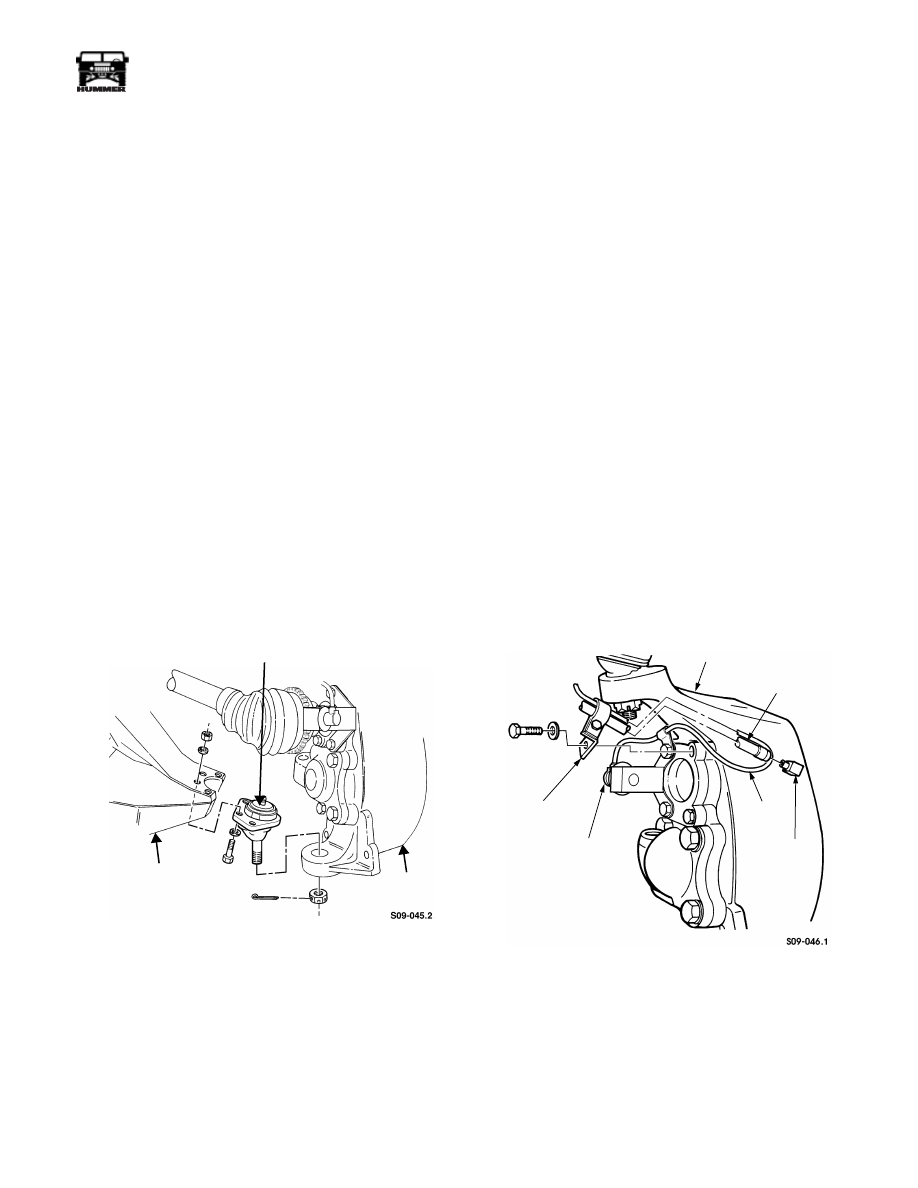
Figure 9-8:   Lower Ball Joint Replacement


UPPER CONTROL ARM REPLACEMENT


NOTE: 


The procedure for removing and installing the front

and rear upper control arms is basically the same. This proce-
dure covers the left front upper control arm.


Removal 


1.

Remove wheel (Section 6).

2.

Remove bolt and washer securing vent line/speed sensor
lead bracket to geared hub (Figure 9-9).

3.

Disconnect vent line from fitting.

4.

Remove speed sensor from sensor mount bracket.

5.

Remove bolt, p-clamp, vent line and speed sensor lead
from upper control arm (Figure 9-10).

6.

Remove cotter pin and slotted nut from upper ball joint. 

7.

Separate upper ball joint from geared hub using ball joint
remover. 

8.

Remove four locknuts, bolts and eight washers securing
upper ball joint to upper control arm and remove upper
ball joint.

9.

Mark position of the eccentric reference holes on the
brackets for installation.

10. Remove two locknuts, washers, eccentrics, bolts, and

upper control arm from brackets and remove upper control
arm. 


Figure 9-9:   Vent Line Connection Replacement

LOWER BALL JOINT

LOWER 

GEARED 

CONTROL ARM

HUB

GEARED HUB

VENT LINE
BRACKET

FITTING

VENT LINE

SENSOR

LEAD

SPEED

SENSOR


9-6

Axles, Suspension, and Frame


___________________________________________


®


Installation 


1.

Install upper control arm on brackets with two washers, 
eccentrics, bolts, and locknuts. Align reference holes 
(from removal step 8) on eccentrics with marks on brack-
ets. Do not tighten locknuts (Figure 9-10).

2.

Secure upper ball joint to upper control arm with four
washers, bolts, and locknuts. Tighten locknuts to 37 lb-ft
(50 N•m).


CAUTION: 


Do not loosen slotted nut to install cotter pin. Do-

ing this may result in damage to equipment.


NOTE: 


When slotted nuts are tightened to prescribed torque

values, cotter pins must have a minimum of 50% engagement
with the nut slots.

3.

Install upper ball joint on geared hub with slotted nut.
Using crowfoot and adapter, tighten slotted nut to 65 lb-ft
(88 N•m). Install cotter pin in slotted nut.

4.

Tighten locknuts on brackets to 260 lb-ft (359 N•m).

5.

Install p-clamp, vent line and speed sensor lead on upper
control arm with bolt.

6.

Connect vent line to fitting (Figure 9-9).

7.

Install speed sensor in sensor bracket.

8.

Secure vent line/speed sensor bracket to geared hub with
clamp, washer, and bolt. Tighten bolt to 37 lb-ft (50 N•m).

9.

Install wheel (Section 6).


Figure 9-10:   Upper Control Arm Assembly Replacement

VENT LINE

ECCENTRIC

UPPER

CONTROL ARM

BRACKET

ECCENTRIC

REFERENCE

HOLE

PIVOT BOLT

PIVOT

BOLT

NUT

FLAT

WASHER

UPPER

BALL

JOINT

UPPER

CONTROL

ARM

GEARED

HUB

SPEED

SENSOR

LEAD

VENT LINE

SPEED SENSOR

P-CLAMP


__________________________________________


 Axles, Suspension, and Frame  9-7


®


05745159


CONTROL ARM BUSHING REPLACEMENT


Removal 


NOTE: 


Control arm bushings must be replaced as a set

(Figure 9-11).

1.

Remove control arm.

2.

Support control arm and press bushing out of control arm.


Installation 


1.

Lubricate outside diameter of bushing with grease.

2.

Insert bushing in control arm (Figure 9-11).

3.

Support control arm and press bushing into control arm
until flange on bushing seats on control arm.

4.

Install control arm.

5.

Adjust caster and camber.


Figure 9-11:   Control Arm Bushing Replacement


LOWER CONTROL ARM REPLACEMENT


NOTE: 


The procedure for removing and installing the front

and rear lower control arms is basically the same. This proce-
dure covers the left front lower control arm.


Removal 


WARNING:  Lower control arm must be supported dur-
ing removal and installation. Failure to support lower
control arm may cause personal injury or damage to
equipment.


1.

Remove wheel (Section 6).

2.

Remove shock absorber.

3.

Remove bolt, two washers, and bar link (front only) from
lower control arm (Figure 9-12).

4.

Remove four locknuts, bolts, and eight washers from
lower ball joint and lower control arm (Figure 9-13).

5.

Raise and support lower control arm. Remove lower ball
joint from arm.

6.

Lower the lower control arm and remove coil spring.

7.

Remove two locknuts, washers, bolts, and lower control
arm from brackets. 


NOTE: 


Removing the lower ball joint from the geared hub

will ease installation.

8.

Remove cotter pin and slotted nut from lower ball joint. 

9.

Separate lower ball joint from geared hub using ball joint
remover. Remove lower ball joint.


Figure 9-12:   Bar Link Replacement

CONTROL ARM

FLANGE

BUSHING

BAR LINK

LOWER CONTROL ARM


9-8

Axles, Suspension, and Frame


___________________________________________


®


Installation 


WARNING:  Lower control arm must be supported dur-
ing removal and installation. Failure to support lower
control arm may cause personal injury or damage to
equipment.


NOTE: 


On lower control arms, bolt heads are toward front of

vehicle.

1.

Install lower control arm on brackets with two bolts, wash-
ers, and locknuts. Do not tighten locknuts  (Figure 9-13).


Figure 9-13:   Lower Control Arm Replacement


2.

Install coil spring on lower control arm ensuring end of
coil spring fits in spring pocket of lower control arm.

3.

Install lower ball joint on lower control arm, ensuring ball
joint is placed below lower control arm.

4.

Secure lower ball joint to lower control arm with four
bolts, locknuts and eight washers. Tighten locknuts to 65
lb-ft (80 N•m).

5.

Install lower ball joint on geared hub with slotted nut.
Tighten slotted nut to 73 lb-ft (99 N•m), and install cotter
pin in slotted nut.

6.

Tighten locknuts on brackets to 260 lb-ft (353 N•m).

7.

Apply thread-locking compound to threads of bolt. Install
bar link on lower control arm with two washers and bolt.
Tighten bolt to 70 lb-ft (95 N•m) (Figure 9-12).

8.

Install shock absorber.

9.

Install wheel (Section 6).


GEARED HUB REPLACEMENT


NOTE: 


Replacement procedures are basically the same for

front and rear geared hubs. This procedure covers the front
geared hub.


Removal 


1.

Remove wheel. 

2.

Remove drainplug from geared hub and drain geared hub
(Figure 9-14).


Figure 9-14:   Geared Hub Drainplug Location


3.

Install drainplug in geared hub.

4.

Remove bolt, washer, and vent line/speed sensor lead
bracket from geared hub (Figure 9-15).

5.

Disconnect vent line from geared hub fitting.

6.

Remove speed sensor from sensor bracket on geared hub.

7.

Remove cotter pin, slotted nut, and washer from tie rod
end. (Figure 9-14).

8.

Using puller J–24319–B, disconnect tie rod end from
geared hub.

9.

Remove access plug, washer, halfshaft retaining bolt,
lockwasher, and halfshaft from geared hub (Figure 9-15).


WARNING:  Geared hub must be supported during re-
moval and installation. Failure to support geared hub
may cause personal injury or damage to equipment.


10. Remove cotter pin and slotted nut from upper ball joint.

Remove ball joint stud from geared hub.

11. Remove cotter pin and slotted nut from lower ball joint.

Remove ball joint stud from geared hub.

12. Lower support and remove geared hub.

BRACKET

COIL

SPRING 

LOWER 

LOWER BALL JOINT

GEARED HUB

SPRING

POCKET

CONTROL 

ARM

SLOTTED NUT

GEARED HUB

TIE ROD END

DRAINPLUG


Content   ..  134  135  136  137   ..