Hummer H1 (2002+). Manual - part 126
_________________________________________________________
Steering System 8-11
®
05745159
IGNITION SWITCH LOCK CYLINDER
REPLACEMENT
Removal
1.
Disconnect battery ground cable.
2.
Remove close-out panel.
3.
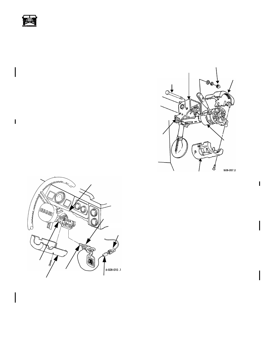
Remove five screws and lower steering column shroud
(Figure 8-16).
4.
Disconnect lock cylinder connector from ignition switch
connector.
5.
Turn ignition switch to RUN position.
6.
Depress lock cylinder detent pin through detent pin hole
and remove lock cylinder from steering column.
Installation
1.
Insert lock cylinder into steering column (Figure 8-16).
2.
Turn ignition switch to LOCK position.
3.
Connect lock cylinder connector to ignition switch
connector.
4.
Secure lower steering column shroud to steering column
with five screws.
5.
Install close-out panel.
6.
Connect battery ground cable.
7.
Verify that ignition switch lock cylinder operates properly.
Figure 8-16: Ignition Switch Lock Cylinder
Replacement
IGNITION INTERLOCK CABLE REPLACEMENT
Removal
1.
Remove five screws and lower shroud from steering col-
umn (Figure 8-17).
Figure 8-17: Steering Column Shrouds
2.
Loosen two locknuts securing steering column to
mounting bracket.
3.
Remove locknut, lockwasher, three washers, and bolt
securing steering column to mounting bracket.
4.
Lower steering column and remove upper shroud.
5.
Remove screw and interlock cable from ignition switch
(Figure 8-18).
6.
Disconnect connector from interlock cable.
7.
Raise and secure hood.
8.
Remove screw securing clamp and interlock cable to
bracket. Remove clamp from interlock cable.
9.
Remove close-out panel (Section 10).
10. Remove shifter (Section 5).
11. Remove nut and screw securing interlock cable to shifter
(Figure 8-19).
12. Remove interlock cable and grommet from vehicle.
STEERING COLUMN
LOCK
LOCK CYLINDER
CONNECTOR
CYLINDER
LOCK CYLINDER
DETENT PIN
LOWER STEERING
COLUMN SHROUD
DETENT
PIN HOLE
IGNITION
SWITCH
CONNECTOR
UPPER SHROUD
LOWER SHROUD
STEERING
MOUNTING BRACKET
COLUMN
10 lb-ft
31 lb-ft (42 N•m)
(14 N•m)
BOLT
4-1-00