Hummer H1 (2002+). Manual - part 119
____________________________________________________________
Brake System 7-35
®
05745159
3.
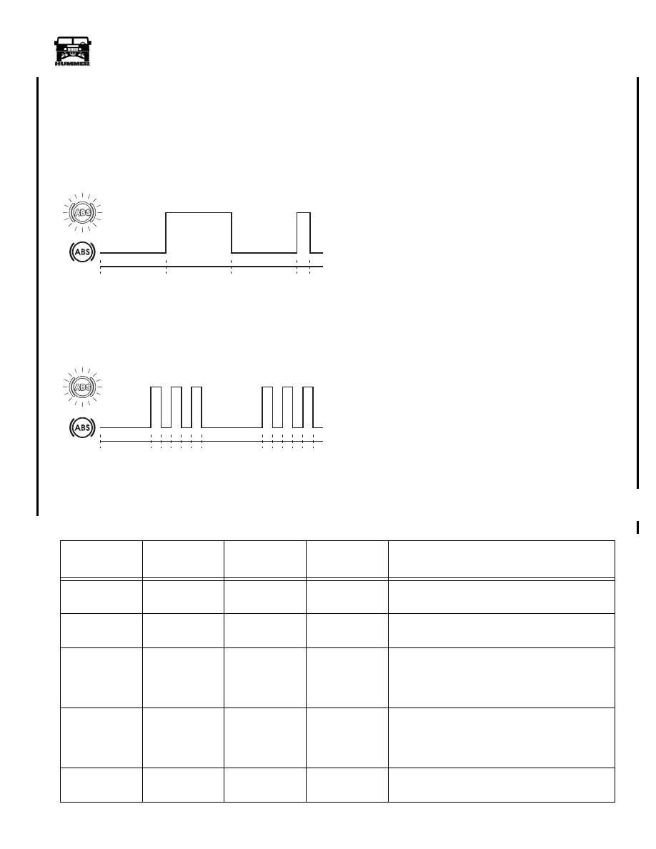
The
start phase
consists of the ABS warning light flashing
in the following sequence (Figure 7-45):
• Pause = 2.5 seconds (long)
• Flash = 2.5 seconds (long)
• Pause = 2.5 seconds (long)
• Flash = 0.5 seconds (short)
Figure 7-45: Blink Code Sequence For Start Phase.
Figure 7-46: Blink Code Sequence For Code 3.3.
4.
The
first part
of the code number (Figure 7-46:): A pause
of 2.5 seconds precedes a series of short flashes. Count the
flashes until the next long pause occurs. The number of
short flashes obtained is the first part of the code number.
5.
The
second part
of the code number: A pause of 2.5
seconds occurs between the first and second parts, before a
series of short flashes occurs. The number of short flashes
forms the second part of the code number.
6.
The sequence of the
start phase
,
first and second parts
will continue until the switch jumper is deactivated.
NOTE:
If you are unsure of the code, do not deactivate the
switch jumper from the DLC because the code for that fault
will be cleared from the memory.
7.
The memory is capable of storing more than one fault. To
search the memory, reconnect the switch jumper and await
the next start phase.
8.
Repeat the procedure until no further faults are stored in
the memory. The memory is cleared when a long pause of
7.5 seconds occurs after the start phase.
Clearing Fault Codes
At the end of a fault code cycle, deactivate the blink code
jumper. The fault code will cycle one more time before the
lamp remains on solid. Turn off the ignition and the fault code
will be cleared from memory.
The fault codes, their causes and repair actions are listed in the
following table.
2.5 sec
2.5 sec
2.5 sec
0.5
sec
8-S07-003
ABS
Warning
Lamp
2.5 sec
8-S07-004
ABS
Warning
Lamp
0.5
sec
0.5
sec
2.5 sec
0.5
sec
0.5
sec
0.5
sec
0.5
sec
Fault Code List - Ignition key “OFF” to test system (except where noted)
Fault Code
Problem Area
Test Pin
Locations
Values
Check/Repair
2-0
ECU internal
failure.
-
-
Replace ECU.
2-1
ECU internal
failure.
-
-
Replace ECU.
2-2
Recirculating
Pump (RCP)
operates contin-
uously.
11 and 27
30 and 27
0 volts
Check the RCP wiring, the pump relay and the
wiring connections. Repair or replace as required.
2-2
RCP does not
operate.
9 and 11
27 and 30
Ignition “ON”
approximate
battery +
voltage.
Check the RCP wiring, the pump relay and fuse
and pump connections. Repair or replace as
required.
2-4
RCP failure
(motor locked).
9, 11 and 12
Ignition “ON”
motor running.
Excessive current failure. If pump does not run
with pins linked, replace modulator.
4-1-00