Hummer H1 (2002+). Manual - part 107
______________
Wheels and Tires/Central Tire Inflation System (CTIS) 6-43
®
05745159
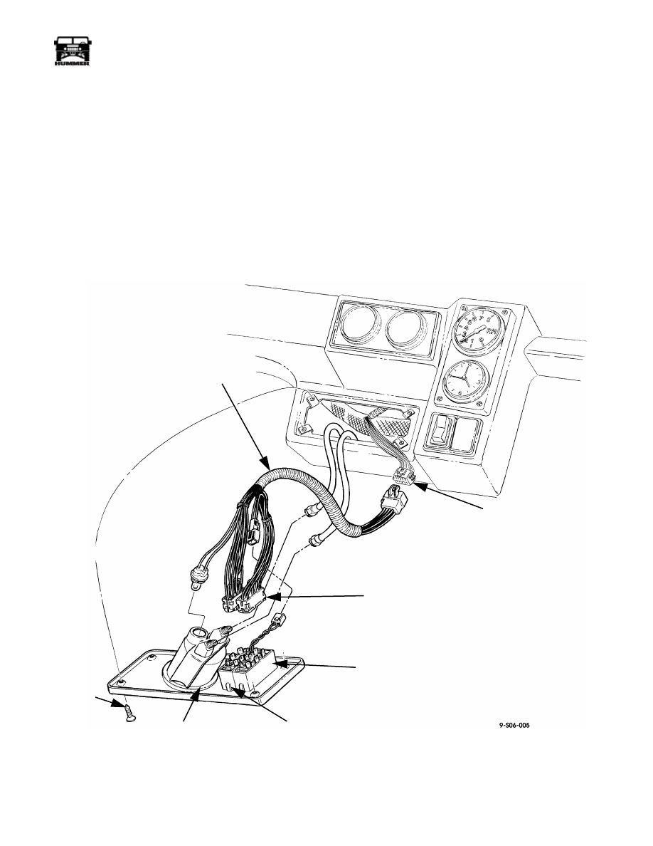
CTIS INTERIOR HARNESS
NOTE: Prior to removal, tag all leads for installation.
Removal
1.
Remove CTIS instrument cluster panel.
2.
Disconnect connector from inflate/deflate and tire selector
switches (Figure 6-60).
3.
Remove lamp from air pressure gauge.
4.
Disconnect harness connector from I/P harness connector
and remove interior harness.
Cleaning and Inspection
Clean and inspect CTIS harness and connectors. Check for de-
fects such as frayed wires and cracks. Repair or replace defec-
tive parts.
Installation
1.
Position interior harness in approximate mounting location
and connect harness connector to I/P harness connector
(Figure 6-60).
2.
Install lamp in air pressure gauge.
3.
Connect connector to inflate/deflate and tire selector
switches.
4.
Install CTIS instrument cluster panel.
Figure 6-60: CTIS Interior Harness Appearance
AIR PRESSURE
GAUGE
SCREW
INFLATE/
TIRE
SELECTOR
SWITCH
SWITCH
CONNECTORS
DEFLATE SWITCH
I/P HARNESS
CONNECTOR
CTIS INTERIOR
HARNESS