Hummer H1 (2002+). Manual - part 63
____________________________________________
Transmission/Transfer Case 5-51
®
05745159
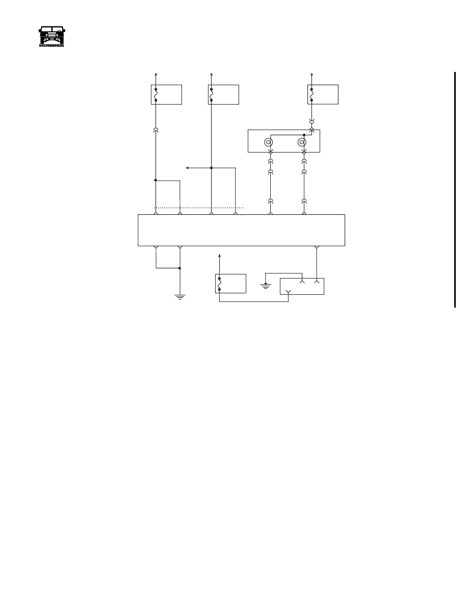
DTC P0560 System Voltage Fault
Circuit Description
Circuit 239 is the voltage feed for the PCM. Circuit 537 is the
battery feed for the PCM.
This DTC detects a low voltage, a high voltage for a long time,
or a high voltage for a short time. This is a type “D” DTC.
Conditions For Setting DTC
System Voltage Low:
• Engine speed is greater than 1500 rpm.
• System voltage is less than 10.5 volts at a maximum
transmission temperature of 152° C (305° F).
• System voltage is less than 6.7 volts at a minimum
transmission temperature of -40° C (-40° F).
• All conditions met for 4 seconds.
System Voltage High:
• System voltage is greater than 19 volts for 4 seconds.
Action Taken When DTC Sets
• The PCM will cause an immediate shift to second gear.
• The PCM will turn off Pressure Control Solenoid.
• The PCM will inhibit converter clutch engagement.
• The PCM will freeze shift adapts.
• The PCM will NOT illuminate the Engine/Trans light.
Conditions For Clearing DTC
• The DTC can be cleared using the scan tool. The DTC
will be cleared when the vehicle has achieved 40 warm-
up cycles without a failure reported.
• The PCM will cancel the DTC default actions when the
fault no longer exists and the ignition is cycled “off”
long enough to power down the PCM.
Diagnostic Aids
• Charging the battery with a battery charger and jump
starting an engine may set DTC(s). If DTC(s) set when
an accessory is operated, check for faulty connections or
excessive current draw.
• Check for loose/damaged terminals at generator.
• Check belt wear/tension.
• If any engine DTCs are present diagnose and clear these
DTCs first. Then check to see if the transmission DTCs
have set.
Test Description
The numbers below refer to the step numbers on the diagnostic
chart.
3.
This test checks charging system voltage.
4.
This test checks battery voltage Input at the PCM.
6.
This test checks ignition voltage input at the PCM.
FUSE 2D
20 AMP
INTERIOR
STS
LAMP
MIL
LAMP
FUSE 3A
20 AMP
EXTERIOR
HOT AT
ALL TIMES
HOT IN RUN
AND START
HOT IN RUN
AND START
FUSE 4B
5 AMP
INTERIOR
G2
G4
FUSE 1H
5 AMP
INTERIOR
DLC
POWERTRAIN
CONTROL
MODULE
SERIAL DATA
CLASS II
MIL
CONTROL
STS LAMP
CONTROL
914 PP
16
4
2
59 BK
C28-C8
570 BK
C28-D7
C28-D6
GROUND
GROUND
570 BK
BATT
BATT
IGN
IGN
C28-C13
C28-D13
C28-C12
C28-C11
C28-D11
TO
C29-B3
537 OR
239 PK
C1-10
C10-J
C10-H
C10-C
C3-G5
C3-F3
C1-25
C1-28
C28-C14
658 BR
714 RD
STATUS
CENTER
HOT AT
ALL TIMES
9-S12-064
554 GRY
30
GR
Y
3-1-01