Hummer H1 (2002+). Manual - part 48


  Index      Hummer     Hummer H1 - service repair manual 2002 year


Search            


Content   ..  46  47  48  49   ..


Hummer H1 (2002+). Manual - part 48


___________________________________________________________


 Cooling System  4-7


®


05745159


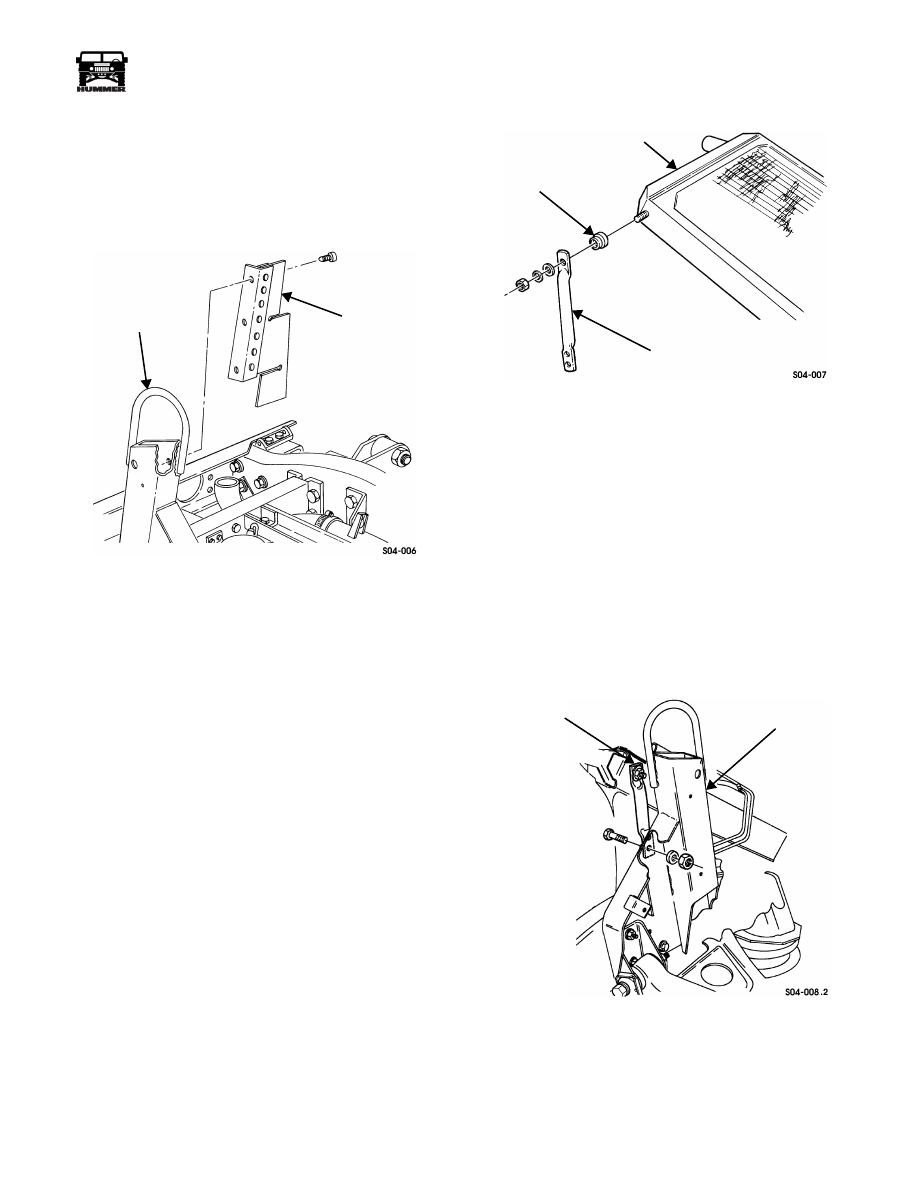
SHROUD SHIELD ASSEMBLY REPLACEMENT


Removal 


1.

Remove radiator and fan shroud.

2.

Remove screws and shroud shield assembly from airlift
bracket (Figure 4-9).


Figure 4-9:   Shroud Shield Assembly Replacement


Installation 


1.

Secure shroud shield assembly to airlift bracket with 
screws (Figure 4-9). 

2.

Install radiator and fan shroud.


RADIATOR REAR SUPPORT BRACKET 
REPLACEMENT


Removal 


1.

Remove left splash shield (Section 10).

2.

Remove battery tray and right splash shield (Section 12).

3.

Remove radiator rear support bracket and insulator from
radiator (Figure 4-10).

4.

Remove support bracket from airlift bracket (Figure 4-11).


Installation 


1.

Fasten radiator rear support bracket to airlift bracket with 
bolts, washers, and locknuts. Do not tighten locknuts  
(Figure 4-11).

2.

Secure insulator and support bracket to radiator with
washers and locknut (Figure 4-10).

3.

Tighten all locknuts to 26 lb-ft (35 N•m).

4.

Install left splash shield (Section 10).

5.

Install battery tray and right splash shield (Section 12).


Figure 4-10:   Insulator and Rear Support Bracket 

Location


SURGE TANK REPLACEMENT


Removal 


1.

Drain cooling system.

2.

Disconnect radiator vent hose from surge tank (Figure 4-12).

3.

Disconnect surge tank-to-lower radiator hose from surge
tank.

4.

Disconnect overflow hose from surge tank.

5.

Disconnect low coolant sensor wiring harness. 

6.

Loosen clamps and remove surge tank from bracket.


Figure 4-11:    Rear Support Bracket Mounting


Installation 


1.

Secure surge tank to bracket with clamps (Figure 4-12).

2.

Connect low coolant sensor wiring harness. 

AIRLIFT BRACKET

SHROUD

SHIELD ASSEMBLY

RADIATOR

INSULATOR

REAR SUPPORT BRACKET

REAR

AIRLIFT BRACKET

 SUPPORT BRACKET


4-8

Cooling System


____________________________________________________________


®


3.

Connect surge tank-to-lower radiator hose to surge tank.

4.

Connect radiator vent hose to surge tank.

5.

Connect overflow hose to surge tank.

6.

Fill and purge cooling system.


Figure 4-12:   Surge Tank Replacement


SURGE TANK-TO-RADIATOR VENT HOSE 
REPLACEMENT


Removal 


1.

Depressurize cooling system.

2.

Loosen two clamps and remove radiator vent hose from
radiator and surge tank (Figure 4-13).

3.

Reclaim coolant. 


Installation 


1.

Secure radiator vent hose to surge tank and radiator with 
two clamps  (Figure 4-13).

2.

Tighten coolant filler cap.

3.

Replace coolant. 


Figure 4-13:   Surge Tank-to-Radiator Vent Hose 

Location


THERMOSTAT BYPASS HOSE REPLACEMENT


Removal 


1.

Drain cooling system.

2.

Loosen two clamps and remove bypass hose from nipples
on water pump and water crossover (Figure 4-14).


Installation 


1.

Secure bypass hose to nipples on water pump and water 
crossover with two clamps (Figure 4-14).

2.

Fill cooling system.


Figure 4-14:   Thermostat Bypass Hose 

Replacement

SURGE TANK

BRACKET

OVERFLOW

HOSE

LOW COOLANT

SENSOR

VENT HOSE FITTING

(HOSE NOT SHOWN)

SURGE TANK-TO-LOWER

RADIATOR HOSE

SURGE TANK

VENT HOSE

RADIATOR

HOSE

WATER PUMP

WATER CROSSOVER

BYPASS

BLEEDER VALVE

NIPPLES


___________________________________________________________


 Cooling System  4-9


®


05745159


UPPER RADIATOR HOSE REPLACEMENT


Removal 


1.

Drain cooling system as necessary. 

2.

Depressurize cooling system.

3.

Loosen clamps and remove hose from thermostat housing
and radiator (Figure 4-15).


Installation 


1.

Secure upper radiator hose to thermostat housing and radi-
ator with clamps (Figure 4-15).

2.

Fill cooling system.


Figure 4-15:   Upper Radiator Hose Location


LOWER RADIATOR HOSE REPLACEMENT


Removal 


1.

Drain cooling system.

2.

Loosen clamps and remove lower radiator hose from
radiator and lower tube assembly (Figure 4-16).


Installation 


1.

Secure lower radiator hose to lower tube assembly and 
radiator with clamps (Figure 4-16).

2.

Fill cooling system.


Figure 4-16:   Lower Radiator Hose Location

RADIATOR

CLAMP

THERMOSTAT

HOUSING

UPPER RADIATOR

HOSE

RADIATOR

LOWER TUBE ASSEMBLY

LOWER

HOSE

RADIATOR


4-10

Cooling System


__________________________________________________________


®


RADIATOR LOWER TUBE ASSEMBLY REPLACEMENT


Removal 


1.

Drain cooling system.

2.

Remove drain valve from lower tube assembly
(Figure 4-17).

3.

Disconnect radiator lower tube assembly from frame
bracket.

4.

Loosen clamp and disconnect water pump inlet hose from
lower tube assembly.

5.

Loosen clamp and disconnect surge tank-to-lower radiator
hose from lower tube assembly.

6.

Loosen clamp and disconnect lower radiator hose from
lower tube assembly.

7.

Remove lower tube assembly.


Installation 


1.

Secure lower tube assembly to frame bracket with bolts, 
washers, and locknuts. Tighten locknuts to 6 lb-ft (8 N•m) 
(Figure 4-17).

2.

Connect lower radiator hose to lower tube assembly and
tighten clamp.

3.

Connect surge tank-to-lower radiator hose to lower tube
assembly and tighten clamp.

4.

Connect water pump inlet hose to lower tube assembly
and tighten clamp.

5.

Apply sealant tape to threads of drain valve and screw
drain valve into lower tube assembly.

6.

Fill cooling system.


Figure 4-17:   Radiator Lower Tube Assembly Location

DRAIN VALVE

LOWER TUBE 

SURGE TANK-TO-

WATER PUMP

FRAME BRACKET

ASSEMBLY

LOWER RADIATOR

HOSE

LOWER

RADIATOR HOSE

 INLET HOSE


Content   ..  46  47  48  49   ..