Hummer H1 (2002+). Manual - part 39


  Index      Hummer     Hummer H1 - service repair manual 2002 year


Search            


Content   ..  37  38  39  40   ..


Hummer H1 (2002+). Manual - part 39


___________________________________________

 Fuel, Emissions, and Exhaust  3-17

®

5745159

Crankshaft Position Sensor

The crankshaft position sensor is a Hall-effect device that mon-
itors crankshaft position and rpm. Four reference teeth 90°
apart, on the crankshaft timing sprocket cause the devise to
turn “ON” or “OFF” producing a digital signal. This occurs as
each tooth passes near the sensor magnetic field turning the
sensor “ON”. The sensor transmits information to the PCM in
the form of a 5 volt digital signal.

A sensor fault will cause a “crank reference missed” reading to
occur. The scan tool will display the number of reference
pulses missed. Normal reading is zero.

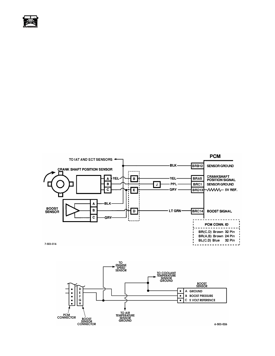
If a sensor fault occurs, check the sensor wiring and connectors
for shorts, opens, grounds, or loose connectors (Figure 3-20).

Sensor Test

1.

Disconnect wires at fuel shut-off solenoid.

2.

Connect voltmeter between PCM terminal BRA5 and
ground and crank engine.

• If meter indicates 5 volts, sensor is OK.

• If meter indicates less than 5 volts or zero volts, check 5 

volt reference at PCM terminal BRD13.

• If 5 volt reference is OK, problem is bad connection or 

failed sensor.

Boost Sensor

The PCM supplies the boost sensor with a 5 volt reference sig-
nal (Figure 3-21). Changes in intake manifold pressure will
cause a change in boost sensor resistance values and voltage.
The PCM determines turbocharger boost by comparing chang-
ing sensor voltage to the original reference voltage.

A sensor failure will result in loss of turbocharger boost and
consequent power decrease. Trouble code P0237 or P0238 will
be set.

Figure 3-20:   Crankshaft Position Sensor Circuit

Figure 3-21:   Boost Sensor Circuit

3-18

Fuel, Emissions, and Exhaust

___________________________________________

®

Boost Sensor Circuit Test

1.

Connect scan tool to diagnostic/data link connector.

2.

Start and run engine at idle speed.

3.

Record boost sensor voltage.

• If voltage is 4.0 volts or more, continue test.

• If voltage is less than specified, compare sensor to 

known good one. Voltage should not vary by more than 
plus or minus 0.4 volt. If sensor voltage compares favor-
ably with known good sensor, problem is in wiring or 
connections.

4.

Turn ignition off and disconnect boost sensor wires.

5.

Turn ignition switch back on (engine off), and note scan
tool voltage reading.

• If boost voltage is 1 volt or less, continue test.

• If voltage is less than specified, problem is in wiring or 

connections between sensor and PCM.

6.

Connect 12 volt test lamp between sensor terminal C and
battery positive post.

• If lamp illuminates, problem is with sensor, connectors, 

or fitting.

• If lamp does not illuminate, problem is open wire.

Boost Sensor Performance Check

This check requires the scan tool to be connected, the engine
running at curb idle rpm, and the transmission in Park.

At idle or at closed throttle decel, a properly functioning sensor
will indicate a pressure reading about the same as barometric
pressure. Sensor voltage (if any), should be low.

Sensor pressure readings should increase as throttle opening is
increased. Voltage readings should also increase.

Boost pressure readings are opposite what you would read for
vacuum. For example, as throttle opening increases, sensor
pressure readings will also increase. Vacuum readings on the
other hand, will decrease as throttle opening increases.

Electronic Accelerator Pedal Tests

The pedal module contains three potentiometer-type sensors
that provide voltage signals to the PCM. Each potentiometer is
scaled differently to provide varying voltage signals. The PCM
compares the voltage variance between them to determine
throttle position (Figure 3-22).

A fault in only one of the potentiometer sensors will not cause
a trouble code to set. Two or more sensors must develop a fault
before the check throttle light will illuminate.

A fault in two sensors will cause the warning light to illuminate
and engine power will be limited by the PCM. A fault in all
three sensors, will cause the PCM to illuminate the light and
limit engine speed idle rpm only.

Trouble codes will set under the following circumstances:

• Two sensors generate voltage of 4.75 volts or more for a 

minimum of two seconds.

• Two sensors generate a voltage of 0.25 volts or less for a 

minimum of two seconds.

• Voltage difference between sensors 1 and 2 of 6% or 

more.

• Voltage difference of 10% or more, between sensors 1, 

2, and 3.

• Fault in all three sensors (above or below normal signal 

voltage).

The Tech 1 scan tool is required for accurate sensor diagnosis.
However, the sensor circuit wires can be tested for shorts,
opens, grounds with 12 volt test lamp and/or multimeter.

Figure 3-22:   Electronic Accelerator Pedal Module Circuitry

___________________________________________

 Fuel, Emissions, and Exhaust  3-19

®

5745159

AIR CLEANER SERVICE

Removal 

NOTE: To remove dust unloader only, perform steps 1 and 2.

1.

Remove air cleaner (Figure 3-23).

2.

Loosen clamp and remove dust unloader from air cleaner
assembly.

3.

Loosen clamp and disconnect elbow from engine side of
air cleaner assembly.

4.

Disconnect vent line from fitting.

5.

Loosen clamp and remove weathercap from air intake
duct.

6.

Remove three capscrews and washers from air intake duct.

7.

Loosen three strap clamps around air cleaner assembly.

8.

Raise air intake duct from air intake support. Loosen
clamp and remove air intake duct and gasket from elbow
and support. Discard gasket.

9.

Remove air cleaner assembly.

10. Remove clamps from air cleaner assembly.

11. Remove fitting, adapter, and tube from air cleaner

assembly.

12. Remove seal from air intake support.

Cleaning and Inspection 

Replace air filter if plugged or saturated with dirt. Clean hose
and dust unloader with shop towels. Clean other components
with solvent and examine for wear or damage. Replace worn,
damaged parts if necessary.

Installation 

1.

Install tube, adapter, and fitting on air cleaner assembly 
(Figure 3-23).

2.

Install dust unloader on air cleaner. Tighten clamp to 44-
53 lb-in. (5-6 N•m).

3.

Install elbow and clamp on air cleaner. Do not tighten
clamp at this time.

4.

Position air cleaner assembly on air intake support and
align elbow with top of support.

5.

Align air cleaner and tighten clamp on elbow to 44-53 lb-
in. (5-6 N•m).

6.

Position air cleaner and strap clamps on support brackets.
Then rotate until elbow clears air intake support.

7.

Install air intake duct and clamp on elbow. Align bolt
holes of air intake duct with holes of air intake support.

8.

Install air intake duct on air intake support. Tighten clamp
to 45-53 lb-in. (5-6 N•m).

9.

Install air cleaner assembly on support brackets and
tighten strap clamps.

10. Connect inlet hose to air horn and air cleaner.

11. Connect vent line to fitting on air cleaner.

12. Install weathercap on air intake duct and tighten clamp to

45-53 lb-in. (5-6 N•m).

13. Install air cleaner shield.

14. Install hood seal on air intake support (if removed).

3-20

Fuel, Emissions, and Exhaust

___________________________________________

®

Figure 3-23:   Air Cleaner Assembly and Dust Unloader

WEATHERCAP

AIR INTAKE

DUCT

VENT LINE

AIR HORN

AIR CLEANER

ASSEMBLY

AIR CLEANER

SHIELD

TUBE

ADAPTER

VENT 

AIR INTAKE

SUPPORT

AIR CLEANER

ASSEMBLY

DUST UNLOADER

ELBOW

SEAL

GASKET

FITTING

AIR INDUCTION

HOSE

HOOD SEAL


Content   ..  37  38  39  40   ..