Hummer H1 (2002+). Manual - part 17


  Index      Hummer     Hummer H1 - service repair manual 2002 year


Search            


Content   ..  15  16  17  18   ..


Hummer H1 (2002+). Manual - part 17


____________________________________________________________________

 Engine  2-29

¨

05745159

REAR MAIN OIL SEAL REPLACEMENT 

1.

Remove transmission and transfer case assembly.

2.

Remove flywheel.

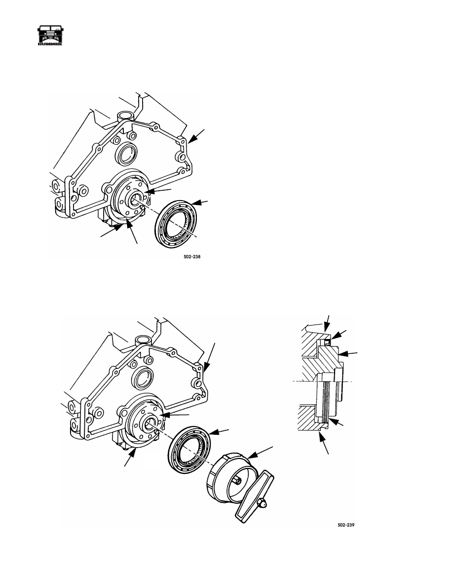
Figure 2-32:   Rear Main Oil Seal Removal

CAUTION:  Do not nick or scratch crankshaft seal surface
when removing old seal (Figure 2-32).

3.

Using small screwdriver or seal puller, remove old seal
from cylinder block and main bearing cap cavity.

4.

Clean old sealant or oil build-up from seal cavity. Check
for excess wear in crank.

5.

Lightly coat crankshaft and inner lip of seal with engine
oil. Lube oil and I.D. of seal.

6.

Position seal on crankshaft with seal lip toward block.
Ensure seal lip does not flip on installation. 

7.

Position seal installer J

Ð

39084 on crankshaft, press seal into

cavity in block, then remove installer tool (Figure 2-33).

8.

Install flywheel on crankshaft. Tighten bolts to 66 lb-ft
(90 N¥m).

9.

Install transmission and transfer case assembly.

10. Run engine and check for leaks after assembly.

Figure 2-33:   Rear Main Oil Seal Installation

BEARING CAP

CRANKSHAFT

SEAL

BLOCK

CAVITY

MAIN BEARING CAP

CRANKSHAFT

SEAL

BLOCK

BLOCK

SEAT SEAL FLUSH

CRANKSHAFT

SEAL

MAIN BEARING CAP

J39084

SEAL INSTALLER

WITH BLOCK

AND BEARING CAP

2-30

Engine

_____________________________________________________________________

¨

ROCKER ARM COVER SERVICE

Right Side Cover Removal 

1.

Remove front console and engine cover.

2.

Remove air horn and inlet hose. Then remove air cleaner
assembly.

3.

Drain radiator.

4.

Remove surge tank.

5.

Disconnect and remove water control valve, hoses, and
bracket.

6.

Remove CDR valve and hose.

7.

Remove bolt that attaches transmission fill tube to
cylinder head.

8.

Remove brackets attaching electrical wire harnesses and
sensors to intake manifold.

9.

Remove nuts attaching fuel injector line clamps to intake
manifold studs.

10. Remove intake manifold and gaskets. Cover cylinder head

intake ports to prevent dirt entry.

11. Disconnect lines at fuel injectors. Cover injectors and cap

lines immediately to prevent dirt entry.

12. Loosen lines at fuel injection pump.

13. Remove studs and bolts attaching rocker arm cover to

cylinder head (Figure 2-34).

14. Tap rocker arm cover with rubber mallet to break sealer

bead and loosen cover. Do not pry cover loose.

15. Move fuel injector lines aside (rotate them out of way).

Or, remove necessary injector lines if unable to move
aside.

CAUTION: Do not bend the fuel lines. The internal coating
could fracture, peel off, and clog the injectors.

16. Remove rocker arm cover.

17. Scrape old silicone sealer off cover. Then clean cover with

parts cleaning solvent. Final-clean sealing surfaces with
brake or electrical contact cleaner. This is necessary to
remove residue left from cleaning solvent and ensure
proper adhesion of new sealer.

18. Clean gasket surfaces of intake manifold and cylinder

head. Be sure surfaces are clean and smooth. Remove
minor nicks or scratches with 220 grit emery cloth.

Figure 2-34:   Rocker Arm Cover Removal/Installation (Right Side)

FASTENER

ROCKER ARM COVER

CYLINDER HEAD

INSTALLATION DIAGRAM

BOLT (2)

STUD (6)

____________________________________________________________________

 Engine  2-31

¨

05745159

Right Side Cover Installation

1.

Clean cover mounting surface of cylinder head with brake 
or contact cleaner and shop towels. This product will 
remove residue from the surface and ensure proper adhe-
sion of new sealer.

2.

If new rocker arm cover is being installed, clean seal
surface with brake or contact cleaner.

3.

Apply sealer to rocker arm cover sealing surface. Make
sealer bead 3/16 in. wide by 1/16 in. thick. Use Loctite
599, Permatex Ultra Copper, or similar quality silicone
sealer. Allow sealer to cure slightly (skin over) before
installation.

4.

Align and install rocker arm cover on cylinder head.

5.

Install rocker arm cover attaching studs and bolts
 (Figure 2-34). Tighten cover fasteners evenly to 13-25 lb-
ft (18-34 N¥m) torque. Start at center and work toward
ends when tightening.

6.

Remove protective covering from injectors and lines.
Then connect lines to injectors and to pump, if removed.
Tighten line fittings to 20-22 lb-ft (27-30 N¥m) torque.

7.

Install intake manifold and new gaskets. A gasket dressing
such as, perfect seal, or Permatex High Tack, can be used
to hold gaskets in place. Tighten manifold bolts and studs
to 31 lb-ft (42 N¥m) torque in sequence  (Figure 2-35).

8.

Install fuel injector line clamps and wire harness brackets
on manifold studs. Tighten retaining nuts to 26 lb-ft (35
N¥m) torque.

9.

Install CDR valve and hose.

10. Install bolt that secures transmission fill tube to cylinder

head.

11. Install water control valve and hoses.

12. Install surge tank.

13. Refill cooling system

14. Start engine and check cover for leaks. Then bleed each

injector by loosening fuel line fitting (at injector), just
enough to purge any trapped air. Stop engine when
complete.

15. Install air cleaner, inlet hose, and air horn.

16. Install engine cover and front console.

17. Top off engine coolant and oil levels if required.

Left Side Cover Removal

1.

Remove front console and engine cover.

2.

Drain engine coolant.

3.

Remove driver side splash shield.

4.

Remove air inlet hose and air horn.

5.

Disconnect radiator upper hoses at thermostat housing and
radiator. Then remove hoses and inlet tube as assembly.

6.

Disconnect fuel pump, remove it from clamp and move
pump aside for working clearance.

7.

Remove nuts attaching harness and sensor brackets to
intake manifold studs.

8.

Remove nuts attaching water valve and bracket. Then
move valve and bracket aside for working clearance.

9.

Remove nuts and washers attaching fuel injection line
clamps to manifold studs. Remove and retain clamps and
fasteners.

10. Remove studs and bolts attaching intake manifold to

cylinder heads. Remove manifold and gaskets. Cover
cylinder head intake ports with shop towels to prevent dirt
entry  (Figure 2-35).

11. Remove screws attaching oil dipstick and tube to cover.

Then rotate tube away from engine for working clearance.

12. Disconnect fuel lines at driver side injectors. Then loosen

(or remove) lines at pump. Rotate lines aside for working
clearance. Cover lines and injectors to prevent dirt entry.

CAUTION:  Do not bend the fuel injector lines. The internal
coating could fracture, peel off, and clog the injectors.

13. Remove rocker arm cover attaching bolts and studs. Then

tap cover with rubber mallet to break sealer bead. Do not
pry cover loose.

14. Remove rocker arm cover.

15. Clean cover in parts cleaning solvent and scrape all traces

of old silicone sealer off cover seal surfaces. Final clean
cover seal surfaces with brake or contact cleaner. This is
necessary to remove residue from cleaning solvent, and
ensure proper adhesion of new sealer.

16. Clean gasket surfaces of intake manifold and cylinder

heads. Be sure surfaces are clean and smooth. Remove
minor nicks or scratches with 220 grit emery cloth.

2-32

Engine

_____________________________________________________________________

¨

Left Side Cover Installation

1.

Clean cover mounting rails on cylinder head with brake or 
contact cleaner and shop towels. This product will remove 
residue from surface and ensure proper adhesion of new 
sealer.

2.

If new rocker arm cover is being installed, clean seal
surface with brake or contact cleaner.

3.

Apply sealer to rocker arm cover sealing surface. Make
sealer bead 3/16 in. wide by 1/16 in. thick. Use Loctite
599, Permatex Ultra Copper, or similar quality silicone
sealer. Allow sealer to cure slightly (skin over) before
installation.

4.

Align and install rocker arm cover on cylinder head.

5.

Install rocker arm cover attaching bolts and studs
(Figure 2-34). Tighten cover fasteners evenly to 13-25 lb-
ft (18-34 N¥m) torque  (Figure 2-35).

6.

Remove protective covering from injectors and lines.
Then connect lines to pump and injectors. Tighten line
fittings to 20-22 lb-ft (27-30 N¥m) torque.

7.

Install intake manifold and new gaskets. A gasket dressing
such as Perfect Seal, or Permatex High Tack, can be used
to hold gaskets in place. Tighten manifold bolts and studs
to 31 lb-ft (42 N¥m) torque.

8.

Install fuel injector line clamps and harness and sensor
brackets on manifold studs. Tighten retaining nuts to 26
lb-ft (35 N¥m) torque.

9.

Attach oil dipstick and tube to cover bracket.

10. Attach water control valve bracket to manifold.

11. Install and connect fuel pump.

12. Connect radiator upper hoses and inlet tube.

13. Refill engine cooling system.

14. Install air inlet hose and air horn.

15. Start engine and check cover for leaks. Then bleed each

injector by loosening fuel line fitting (at injector), just
enough to purge trapped air. Stop engine when complete.

16. Install engine cover and console.

17. Top engine coolant and oil levels if required.

Figure 2-35:   Left Side Rocker Arm Cover

FUEL DRAINBACK LINE

ROCKER ARM COVER

CYLINDER HEAD


Content   ..  15  16  17  18   ..