Hummer H1 (1992-1998). Manual - part 51


  Index      Hummer     Hummer H1 - service repair manual 1992-1998 year


Search            


Content   ..  49  50  51  52   ..


Hummer H1 (1992-1998). Manual - part 51


2-41. ENGINE ASSEMBLY FROM SUBASSEMBLIES (Cont’d)

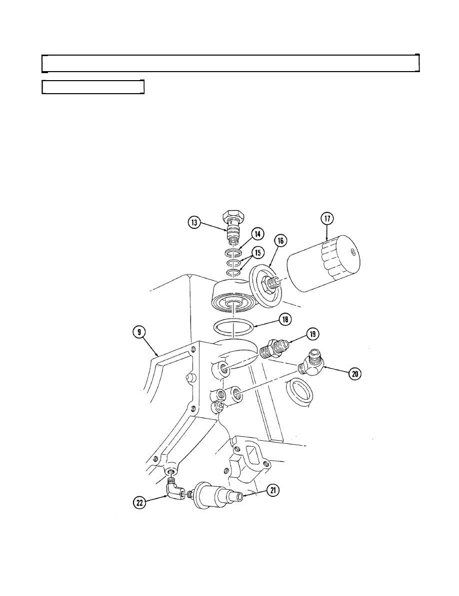
i. Oil Filter and Adapter

1. Install two O-rings (15) on adapter bolt (13).

2. Install O-ring (18) on adapter (16).
3. Install adapter (16) on cylinder block (9) with adapter bolt (13) and gasket (14). Tighten adapter

bolt (13) to 40 lb-ft (54 N•m).

4. Install oil filter (17) on adapter (16). Tighten oil filter (17) until gasket contacts adapter (16) and

tighten an additional 1/2 to 3/4 turn.

5. Coat threads on fitting (22) with pipe sealing compound and install in cylinder block (9).

6. Coat threads on oil pressure sending unit (21) with pipe sealing compound and install in fitting (22).
7. Coat threads on cooler line adapters (19) and (20) with pipe sealing compound ad insall in cylinder.

block (9).

2-167

2-41. ENGINE ASSEMBLY FROM SUBASSEMBLIES (Cont’d)

j. Fuel Pump

1. Apply OE/HDO to pushrod (8) and install into cylinder block (1).

2. Install gasket (2) and adapter plate (3) on cylinder block (1) with two capscrews (4). Tighten

capscrews (4) to 48-84 lb-in. (5-10 N•m).

3. Install gasket (5) and fuel pump (6) on adapter plate (3) with two capscrews (7). Tighten

capscrews (7) to 20-30 lb-ft (27-41 N•m).

2-168

Change 1

2-169

2 - 4 1 . ENGINE ASSEMBLY FROM SUBASSEMBLIES (Cont’d)

k. Oil Pump Drive

1.

Rotate cylinder block (1) 180 degrees.

2.

Install gasket (11) and oil pump drive (10) into cylinder block (1).

3.

Secure oil pump drive (10) with clamp (12) and capscrew (9). Tighten capscrew (9) to 25-37 lb-ft
(34-50 N

m).

6.5L TURBO

2-41. ENGINE ASSEMBLY FROM SUBASSEMBLIES 

(Cont’d)

l. Fuel Injection Pump

1.

2.

3.
4.
5.
6.
7.

8.

Install gasket (5) and injection pump (6) on timing gear cover (3).

Install accelerator cable bracket (12) on fuel injection pump (6) with two capscrews (11). Tighten
capscrews (11) to 13 lb-ft (18 N•m).
Install idle return spring (8) on throttle lever (7) and accelerator cable bracket (12).
Align timing marks (4) on injection pump (6) and timing gear cover (3).
Install injection pump (6) to timing gear cover (3) with three washers (10) and nuts (9).
Rotate crankshaft until timing mark (14) on pump drive gear (13) is straight up.
Align timing marks (14) on pump drive gear (13) and pump driven gear (2) and install driven
gear (2) into timing gear cover (3).
Install three capscrews (1) on driven gear (2) and tighten capscrews (1) to 13-20 lb-ft (18-27 N•m).

2-170


Content   ..  49  50  51  52   ..