Index Hummer Hummer H1 - service repair manual 1992-1998 year
Search
Content .. 17 18 19 20 ..
Hummer H1 (1992-1998). Manual - part 19
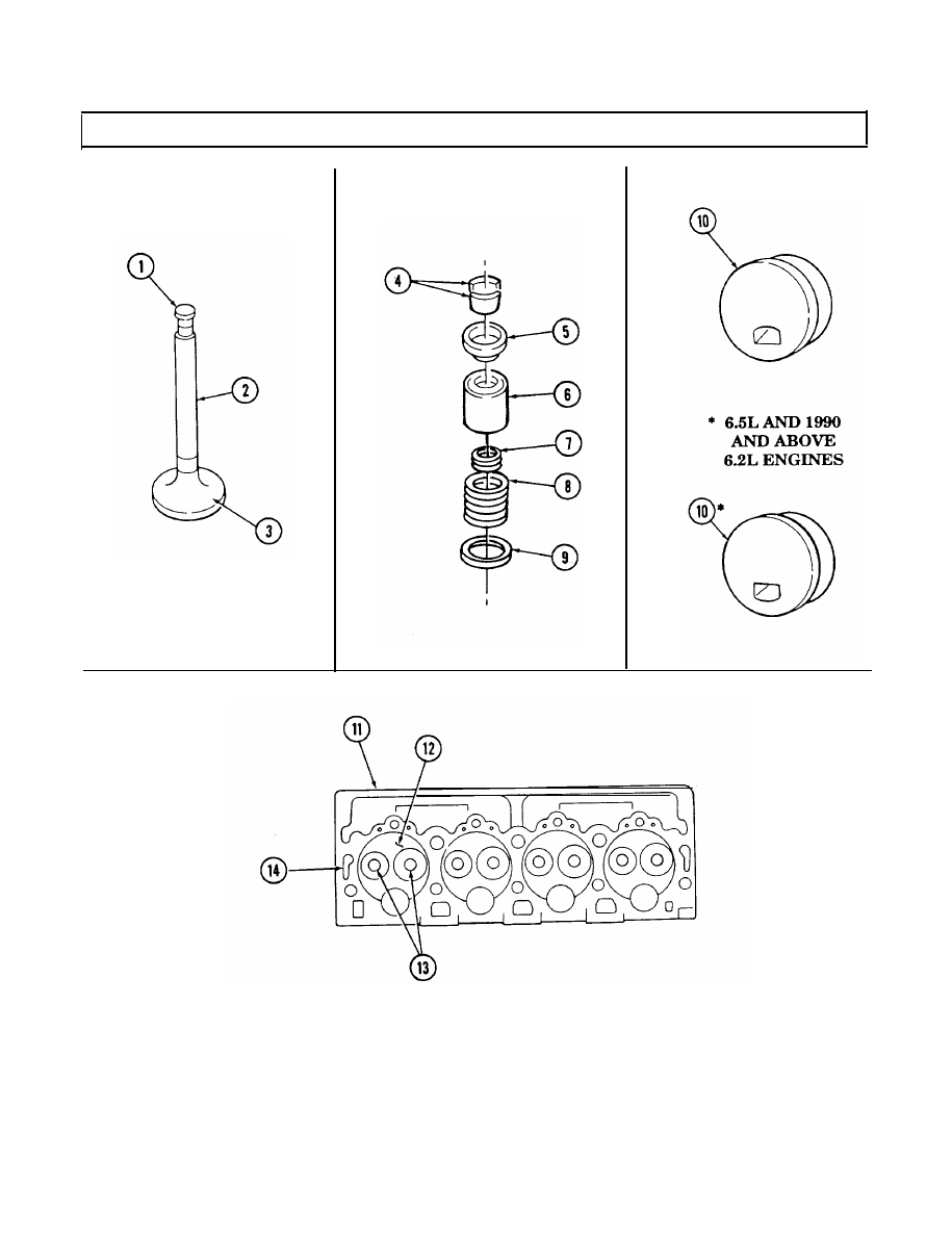
2-21. CYLINDER HEAD AND VALVE REPAIR (Cont’d)
2-65