Honda Pilot (2024 year). Manual in english - page 23
 

  Index      Manuals     Honda Pilot (2024 year). Manual in english


Search            copyright infringement  


Content      ..     21      22      23      24     ..


Honda Pilot (2024 year). Manual in english - page 23


Continued

741

uu

If a Tire Goes Flat

u

Changing a Flat Tire

Han

d

lin
g the U

n

expected

4.

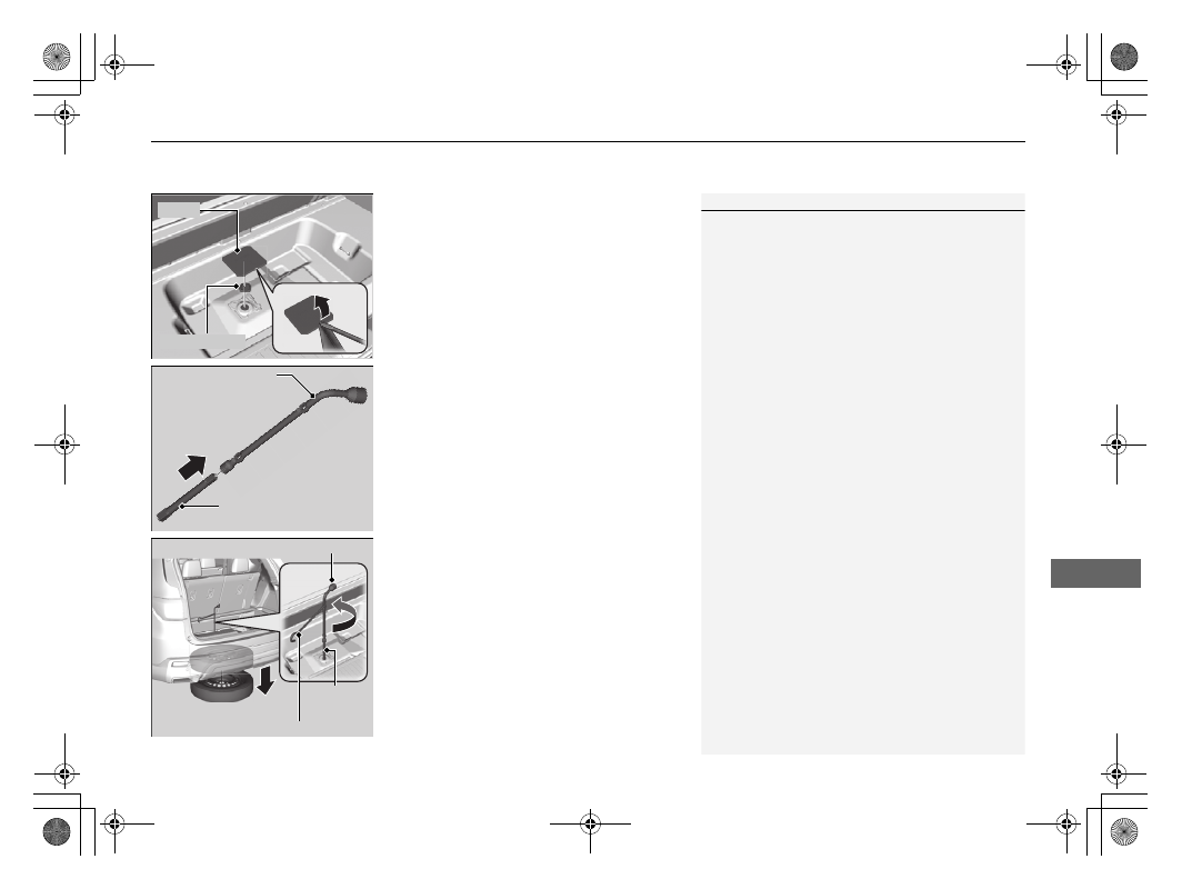
Use a flat-tip screwdriver and remove the 
cover.
Remove the rubber plug on the cargo area 
lining to access the shaft for the spare tire 
hoist.

u

Wrap the flat-tip screwdriver with a 
cloth to prevent scratches.

5.

Connect the wheel nut wrench with the 
box wrench.

6.

Put the wheel nut wrench with the jack 
handle bar on the hoist shaft.
Turn the wrench to the left to lower the 
spare tire to the ground.

1

Getting Ready to Replace the Flat Tire

The wheel nut wrench supplied with your vehicle is 
specially adapted to fit the hoist shaft. Do not use any 
other tool.

Cover

Rubber Plug

Wheel Nut Wrench

Box Wrench

Jack Handle Bar

Wheel Nut Wrench

Box 
Wrench

742

uu

If a Tire Goes Flat

u

Changing a Flat Tire

Han

d

lin
g the U

n

expected

7.

Keep turning the wheel nut wrench to 
create slack in the cable.

8.

Remove the bracket from the spare tire.

9.

Place a wheel block or rock in front and 
rear of the wheel diagonal to the flat tire.

10.

Place the spare tire (wheel side up) under 
the vehicle body, near the tire that needs 
to be replaced.

Bracket

Wheel 
Blocks

The tire to be replaced.

743

uu

If a Tire Goes Flat

u

Changing a Flat Tire

Continued

Han

d

lin
g the U

n

expected

11.

Loosen each wheel nut about one turn 
using the wheel nut wrench.

uu

If a Tire Goes Flat

u

Changing a Flat Tire

744

Han

d

lin
g the U

n

expected

1.

Place the jack under the jacking point 
closest to the tire to be changed.

2.

Turn the end bracket clockwise as shown in 
the image until the top of the jack contacts 
the jacking point.

u

Make sure that the jacking point tab is 
resting in the jack notch.

How to Set Up the Jack

1

How to Set Up the Jack

Do not use the jack with people or luggage in the 
vehicle.

Use the jack provided in your vehicle.
Other jacks may not support the weight (“load”) or 
may not fit the jacking point.

The following instructions must be followed to use 
the jack safely:

Do not use while the engine is running.

Use only where the ground is firm and level.

Use only at the jacking points.

Do not get in the vehicle while using the jack.

Do not put anything on top of or underneath the 
jack.

3

WARNING

The vehicle can easily roll off the jack, 
seriously injuring anyone underneath.

Follow the directions for changing a tire 
exactly, and never get under the vehicle 
when it is supported only by the jack.

Jacking Points

745

uu

If a Tire Goes Flat

u

Changing a Flat Tire

Continued

Han

d

lin
g the U

n

expected

3.

Raise the vehicle, using the jack handle bar 
and the jack handle, until the tire is off the 
ground.

Jack Handle Bar

Wheel Nut Wrench as Jack Handle

uu

If a Tire Goes Flat

u

Changing a Flat Tire

746

Han

d

lin
g the U

n

expected

1.

Remove the wheel nuts and flat tire.

2.

Wipe the mounting surfaces of the wheel 
with a clean cloth.

3.

Mount the spare tire.

4.

Screw the wheel nuts until they touch the 
lips around the mounting holes, then stop 
rotating.

5.

Lower the vehicle and remove the jack. 
Tighten the wheel nuts in the order 
indicated in the image. Go around 
tightening the nuts two to three times in 
this order.

Wheel nut torque:

94 lbf∙ft (127 N∙m, 13 kgf∙m)

Replacing the Flat Tire

1

Replacing the Flat Tire

Do not over tighten the wheel nuts by applying extra 
torque using your foot or a pipe.

Wheel 
Nut

Continued

747

uu

If a Tire Goes Flat

u

Changing a Flat Tire

Han

d

lin
g the U

n

expected

1.

Put the flat tire in the tire storage bag 
provided with your vehicle.

u

The tire storage bag is in the tool case.

2.

Knot the top of the tire storage bag.

3.

Securely put the jack, wheel nut wrench, 
jack handle bar, and box wrench back in 
the tool case.

4.

Bore through the bag, and pass the holding 
belt through the hole of the bag and the 
wheel of the flat tire as shown.

5.

Place the cargo floor lid in the lower 
position.

2

Under-floor Storage Area

 P. 269

6.

Place the flat tire in the cargo area, and 
thread the belt through the rear anchor as 
shown.

7.

Pass the belt through the ring, and tighten 
the belt to secure the flat tire in place.

Storing the Flat Tire

Models with compact spare tire

1

Storing the Flat Tire

3

WARNING

Loose items can fly around the interior in a 
crash and can seriously injure the 
occupants.
Store the wheel, jack, and tools securely 
before driving.

Belt

Rear Anchor

uu

If a Tire Goes Flat

u

Changing a Flat Tire

748

Han

d

lin
g the U

n

expected

1.

Remove the center cap and place the flat 
tire face up under the hoist.

2.

Insert the hoist bracket into the center hole 
of the flat tire.

3.

Connect the wheel nut wrench with the 
box wrench.

4.

Slowly turn the wheel nut wrench clockwise 
to take up the hoist cable slack.
Make sure the bracket is seated in the 
center hole of the flat tire.

5.

Turn the wheel nut wrench with the jack 
handle bar clockwise until the flat tire rests 
against the underbody of the vehicle and 
you hear the hoist click.

6.

Securely put the jack, wheel nut wrench, 
jack handle bar, and box wrench back in 
the tool case.

Storing the Flat Tire

Models with full-size spare tire

1

Storing the Flat Tire

3

WARNING

Loose items can fly around the interior in a 
crash and can seriously injure the 
occupants.
Store the jack and tools securely before 
driving.

Center Cap

Jack Handle Bar

Wheel Nut Wrench

Box 
Wrench

749

uu

If a Tire Goes Flat

u

Changing a Flat Tire

Han

d

lin
g the U

n

expected

If you replace a flat tire with the spare tire, the low tire pressure/TPMS indicator 
comes on while you are driving. After driving for a few miles (kilometers), 

Tire 

pressure monitor system problem

 will appear on the driver information interface 

and the indicator will start blinking for a short time and then stay on; however, this 
is normal and is no cause for concern.

If you replace the tire with a regular tire, the warning message on the driver 
information interface and the low tire pressure/TPMS indicator will go off after a few 
miles (kilometers).

TPMS with Tire Fill Assist and the Spare Tire

1

TPMS with Tire Fill Assist and the Spare Tire

The system cannot monitor the pressure of the spare 
tire. Manually check the spare tire pressure to be sure 
that it is correct.

Use the TPMS specific wheels. Each is equipped with 
a tire pressure sensor mounted inside the tire behind 
the valve stem.

750

Han

d

lin
g the U

n

expected

Engine Does Not Start

Checking the Engine

If the engine does not start, check the starter.

If you cannot start the engine after checking all the items in the list above, have your vehicle checked by a dealer.

Starter condition

Checklist

Starter doesn’t turn or turns 
over slowly.

The battery may be dead. Check 
each of the items on the right and 
respond accordingly.

Check for a message on the driver information interface.

If the 

To start, touch start button with emblem side of remote

 message appears

2

If the Keyless Remote Battery is Weak

 P. 752

Check the fuses.

Check all fuses, or have your vehicle checked by a dealer.

2

Inspecting and Changing Fuses

 P. 771

The starter turns over normally 
but the engine doesn’t start.

There may be a problem with a 
fuse. Check each of the items on 
the right and respond accordingly.

Review the engine start procedure.

Follow its instructions, and try to start the engine again.

2

 Starting the Engine

 P. 512

Check the immobilizer system indicator.

When the immobilizer system indicator is blinking, the engine cannot be started.

2

Immobilizer System

 P. 207

2

Immobilizer System Indicator

 P. 112

Check the fuel level.

There should be enough fuel in the tank.

2

 Fuel Gauge

 P. 122

Check the fuses.

Check all fuses, or have your vehicle checked by a dealer.

2

Inspecting and Changing Fuses

 P. 771

If the problem continues:

2

Emergency Towing

 P. 773

751

uu

Engine Does Not Start

u

Checking the Engine

Han

d

lin
g the U

n

expected

If you must start the vehicle immediately, use an assisting vehicle or booster battery 
to jump start it.

2

If the Battery Is Dead

 P. 755

Depending on the situation, it may be possible to temporarily start the engine using 
the emergency start procedure.

2

Emergency Engine Start

 P. 753

752

uu

Engine Does Not Start

u

If the Keyless Remote Battery is Weak

Han

d

lin
g the U

n

expected

If the Keyless Remote Battery is Weak

If the beeper sounds, the 

To start, touch start button with emblem side of 

remote

 message appears on the driver information interface, the 

ENGINE START/

STOP

 button flashes, and the engine won’t start, start the engine as follows:

1.

Press the 

ENGINE START/STOP

 button.

u

The beeper sounds and the 

ENGINE 

START/STOP

 button flashes for about 

30 seconds.

2.

Touch the center of the 

ENGINE START/

STOP

 button with the 

H

 logo on the keyless 

remote while the 

ENGINE START/STOP


button is flashing. The buttons on the 
keyless remote should be facing you.

u

The beeper sounds, and the 

ENGINE 

START/STOP

 button stays on for about 

10 seconds.

3.

Depress the brake pedal and press the 

ENGINE START/STOP

 button while the 

ENGINE START/STOP

 button is on.

u

The engine starts.

u

If you don’t depress the pedal, the mode 
will change to ACCESSORY.

753

uu

Engine Does Not Start

u

Emergency Engine Start

Han

d

lin
g the U

n

expected

Emergency Engine Start

If the engine cannot start using the normal starting procedure, you may be able to 
start it using the emergency start procedure below.
Do not use this procedure if it is not an emergency.

1.

Make sure the parking brake is applied.

2.

Check that the transmission is in 

(

P

, then set the power mode to ACCESSORY.

3.

Firmly depress the brake pedal, then press and hold the 

ENGINE START/STOP


button for at least 15 seconds.

This should be considered a system malfunction even if you are able to start the 
engine using the above procedure.
Have your vehicle checked by a dealer immediately.

754

uu

Engine Does Not Start

u

Emergency Engine Stop

Han

d

lin
g the U

n

expected

Emergency Engine Stop

The 

ENGINE START/STOP

 button may be used to stop the engine due to an 

emergency situation even while driving. If you must stop the engine, do either of the 
following operations:

Press and hold the 

ENGINE START/STOP

 button for about two seconds.

Firmly press the 

ENGINE START/STOP

 button three times.

The steering wheel will not lock. However, because turning off the engine disables 
the power assist the engine provides to the steering and braking systems, it will 
require significantly more physical effort and time to steer and slow the vehicle. Use 
both feet on the brake pedal to slow down the vehicle and stop immediately in a 
safe place.

The gear position automatically changes to 

(

P

 after the vehicle comes to a complete 

stop. Then, the power mode changes to VEHICLE OFF.

1

Emergency Engine Stop

NOTICE

Do not press the 

ENGINE START/STOP

 button while 

driving unless it is absolutely necessary for the engine 
to be turned off.
If you press the 

ENGINE START/STOP

 button while 

driving, the beeper sounds.

755

Continued

Han

d

lin
g the U

n

expected

If the Battery Is Dead

Jump Starting Procedure

Turn off the power to electric devices, such as audio and lights. Turn off the engine, 
then open the hood.

1.

Connect the first jumper cable to your 
vehicle’s battery 

+

 terminal.

2.

Connect the other end of the first jumper 
cable to the booster battery 

+

 terminal.

u

Use a 12-volt booster battery only.

u

When using an automotive battery 
charger to boost your 12-volt battery, 
select a lower charging voltage than 15-
volt. Check the charger manual for the 
proper setting.

3.

Connect the second jumper cable to the 
booster battery 

-

 terminal.

4.

Connect the other end of the second 
jumper cable to the ground bolt as shown. 
Do not connect this jumper cable to any 
other part.

5.

If your vehicle is connected to another 
vehicle, start the assisting vehicle’s engine 
and increase its RPM slightly.

6.

Attempt to start your vehicle’s engine. If it 
turns over slowly, check that the jumper 
cables have good metal-to-metal contact.

1

Jump Starting Procedure

Securely attach the jumper cables clips so that they 
do not come off when the engine vibrates. Be careful 
not to tangle the jumper cables or allow the cable 
ends to touch each other while attaching or 
detaching the jumper cables.

Battery performance degrades in cold conditions and 
may prevent the engine from starting.

3

WARNING

A battery can explode if you do not follow 
the correct procedure, seriously injuring 
anyone nearby.

Keep all sparks, open flames, and smoking 
materials away from the battery.

Booster Battery

uu

If the Battery Is Dead

u

Jump Starting Procedure

756

Han

d

lin
g the U

n

expected

Once your vehicle’s engine has started, remove the jumper cables in the following 
order:

1.

Disconnect the jumper cable from your vehicle’s ground bolt.

2.

Disconnect the other end of the jumper cable from the booster battery 

-


terminal.

3.

Disconnect the jumper cable from your vehicle’s battery 

+

 terminal.

4.

Disconnect the other end of the jumper cable from the booster battery 

+


terminal.

Have your vehicle inspected by a nearby service station or a dealer.

What to Do After the Engine Starts

1

Jump Starting Procedure

The Vehicle Stability Assist

TM

 (VSA

®

) system, Adaptive 

Cruise Control (ACC) with Low Speed Follow, brake 
system (amber), and safety support indicators may 
come on in amber along with a message in the driver 
information interface when you set the power mode 
to ON after reconnecting the battery.
Drive a short distance at more than 12 mph (20 km/h). 
Each indicator should go off. If any do not, have your 
vehicle checked by a dealer.

757

Continued

Han

d

lin
g the U

n

expected

Overheating

How to Handle Overheating

Overheating symptoms are as follows:

The temperature gauge is at the 

 mark or the engine suddenly loses power.

The 

Engine temperature too hot. Do not drive. Allow engine to cool.


message appears on the driver information interface.

Steam or spray comes out of the engine compartment.

First thing to do

1.

Immediately park the vehicle in a safe place.

2.

Turn off all accessories and turn on the hazard warning lights.

u

No steam or spray present: 

Keep the engine running and open the hood.

u

Steam or spray is present: 

Turn off the engine and wait until it subsides. 

Then, open the hood.

1

How to Handle Overheating

NOTICE

Continuing to drive with the temperature gauge at 
the 

 mark may damage the engine.

NOTICE

Continuing to drive with the 

Engine temperature 

too hot. Do not drive. Allow engine to cool.


message on the driver information interface may 
damage the engine.

3

WARNING

Steam and spray from an overheated 
engine can seriously scald you.

Do not open the hood if steam is coming 
out.

Models with B-type meter

H

All models

Models with B-type meter

H

All models

uu

Overheating

u

How to Handle Overheating

758

Han

d

lin
g the U

n

expected

Next thing to do

1.

Check that the cooling fan is operating and 
stop the engine once the 

Engine 

temperature too hot. Do not drive. 
Allow engine to cool.

 message on the 

driver information interface disappears.

u

If the cooling fan is not operating, 
immediately stop the engine.

2.

Once the engine has cooled down, inspect 
the coolant level and check the cooling 
system components for leaks.

u

If the coolant level in the reserve tank is 
low, add coolant until it reaches the 

MAX

 mark.

u

If there is no coolant in the reserve tank, 
check that the radiator is cool. Remove 
the engine compartment cover. Cover 
the radiator cap with a heavy cloth and 
open the cap. If necessary, add coolant 
up to the base of the filler neck, and put 
the cap back on.

2

Engine Compartment Cover

 P. 696

Last thing to do

Once the engine has cooled sufficiently, restart it and check the driver information 
interface.
If the 

Engine temperature too hot. Do not drive. Allow engine to cool.


message does not appear, resume driving. If it appears again, contact a dealer for 
repairs.

1

How to Handle Overheating

If the coolant is leaking, contact a dealer for repairs.

Use water as an emergency/temporary measure only. 
Have a dealer flush the system with proper antifreeze 
as soon as possible.

3

WARNING

Removing the radiator cap while the 
engine is hot can cause the coolant to spray 
out, seriously scalding you.

Always let the engine and radiator cool 
down before removing the radiator cap.

MAX

MIN

Reserve 
Tank

759

Han

d

lin
g the U

n

expected

Indicator Coming On/Blinking

If the Engine oil pressure low Warning Appears

Reasons for the warning to appear

Appears when the engine oil pressure is low.

What to do as soon as the warning 
appears

1.

Immediately park the vehicle on level 
ground in a safe place.

2.

If necessary, turn the hazard warning lights 
on.

What to do after parking the vehicle

1.

Stop the engine and let it sit for 
approximately three minutes.

2.

Open the hood and check the oil level.

u

Add oil as necessary.

2

Oil Check

 P. 698

3.

Start the engine and check the 

Engine oil 

pressure low

 warning.

u

The warning disappears: Start driving 
again.

u

The warning does not disappear within 
10 seconds: Immediately stop the engine 
and contact a dealer for repairs.

1

If the 

Engine oil pressure low

 Warning Appears

NOTICE

Running the engine with low oil pressure can cause 
serious mechanical damage almost immediately.

760

uu

Indicator Coming On/Blinking

u

If the Charging System Indicator Comes On

Han

d

lin
g the U

n

expected

If the Charging System Indicator Comes On

Reasons for the indicator to come on

Comes on when there is a problem with the charging system.

What to do when the indicator comes on

Stop in a safe place and have your vehicle checked by a dealer 
immediately.

If the Malfunction Indicator Lamp Comes On or Blinks

Reasons for the indicator lamp to come on or blink

Comes on when there is a problem with the engine emissions control 
system.

Blinks when engine misfiring is detected.

What to do when the indicator lamp comes on

Avoid high speeds and immediately get your vehicle inspected at a 
dealer.

What to do when the indicator lamp blinks

Park the vehicle in a safe place with no flammable items and wait at least 
10 minutes or more with the engine stopped until it cools.

1

If the Charging System Indicator Comes On

If you need to stop temporarily, do not turn off the 
engine. Restarting the engine may rapidly discharge 
the battery.

1

If the Malfunction Indicator Lamp Comes On or Blinks

NOTICE

If you drive with the malfunction indicator lamp on, 
the emissions control system and the engine could be 
damaged.

If the malfunction indicator lamp blinks again when 
restarting the engine, drive to the nearest dealer at 
31 mph (50 km/h) or less. Have your vehicle 
inspected.

761

uu

Indicator Coming On/Blinking

u

If the Brake System Indicator (Red) Comes On or Blinks

Han

d

lin
g the U

n

expected

If the Brake System Indicator (Red) Comes On or 
Blinks

Reasons for the indicator to come on

The brake fluid is low.

There is a malfunction in the brake system.

What to do when the indicator comes on while driving

Depress the brake pedal lightly to check pedal pressure.

If normal, check the brake fluid level the next time you stop.

If abnormal, take immediate action. If necessary, downshift the 
transmission to slow the vehicle using engine braking.

Reasons for the indicator to blink

There is a problem with the electric parking brake system.

What to do when the indicator blinks

Avoid using the parking brake and have your vehicle checked by a 
dealer immediately.

1

If the Brake System Indicator (Red) Comes On or Blinks

Have your vehicle repaired immediately.
It is dangerous to drive with low brake fluid. If there 
is no resistance from the brake pedal, stop 
immediately in a safe place. If necessary, downshift 
the gears.

If the brake system indicator (red) and 

ABS

 indicator 

come on simultaneously, the electronic brake 
distribution system is not working. This can result in 
vehicle instability under sudden braking.
Have your vehicle inspected by a dealer immediately.

If the brake system indicator (red) blinks at the same 
time when the brake system indicator (amber) comes 
on, the parking brake may not work.
Avoid using the parking brake and have your vehicle 
checked by a dealer immediately.

2

If the Brake System Indicator (Red) Comes 
On or Blinks at the Same Time When the 
Brake System Indicator (Amber) Comes On


P. 763

U.S.

Canada

762

uu

Indicator Coming On/Blinking

u

If the Electric Power Steering (EPS) System Indicator Comes On

Han

d

lin
g the U

n

expected

If the Electric Power Steering (EPS) System Indicator 
Comes On

Reasons for the indicator to come on

Comes on when there is a problem with the EPS system or Driver 
Attention Monitor System.

What to do when the indicator comes on

Stop the vehicle in a safe place and restart the engine.
If the indicator comes on and stays on, immediately have your vehicle 
inspected by a dealer.

If 

Do not drive

 displays on the driver information interface, 

immediately stop in a safe place and contact a dealer.

763

uu

Indicator Coming On/Blinking

u

If the Brake System Indicator (Red) Comes On or Blinks at the Same Time When the Brake System Indicator (Amber) Comes On

Han

d

lin
g the U

n

expected

If the Brake System Indicator (Red) Comes On or 
Blinks at the Same Time When the Brake System 
Indicator (Amber) Comes On

If the brake system indicator (red) comes on or blinks at the 

same time when the brake system indicator (amber) comes on, 
release the parking brake manually or automatically

2

Parking Brake

 P. 641

If the brake system indicator (red) continuously comes on or blinks at 

the same time when the brake system indicator (amber) comes on, 
stop the vehicle in a safe place and have it inspected by a dealer 
immediately.

u

To prevent the vehicle from moving, put the transmission into 

(

P

.

If only the brake system indicator (red) is turned off, avoid using the 

parking brake and have your vehicle checked by a dealer immediately.

1

If the Brake System Indicator (Red) Comes On or Blinks at the Same 
Time When the Brake System Indicator (Amber) Comes On

If you apply the parking brake, you may not be able 
to release it.

If the brake system indicator (red) and the brake 
system indicator (amber) come on at the same time, 
the parking brake is working.

If the brake system indicator (red) blinks at the same 
time when the brake system indicator (amber) comes 
on, the parking brake may not work because it is 
checking the system.

U.S.

Canada

(Red)

U.S.

Canada

(Amber)

764

uu

Indicator Coming On/Blinking

u

If the Low Tire Pressure/TPMS Indicator Comes On or Blinks

Han

d

lin
g the U

n

expected

If the Low Tire Pressure/TPMS Indicator Comes On or 
Blinks

Reasons for the indicator to come on or blink

A tire pressure is significantly low. If there is a problem with the TPMS 
with Tire Fill Assist or the spare tire is installed, the indicator blinks for 
about one minute, and then stays on.

What to do when the indicator comes on

Drive carefully and avoid abrupt cornering and hard braking.
Stop your vehicle in a safe place. Check the tire pressure and adjust the 
pressure to the specified level. The specified tire pressure is on a label on 
the driver side doorjamb.

What to do when the indicator blinks, then remains on

Have the tire inspected by a dealer as soon as possible. If the spare tire 
causes the indicator to blink, change the tire to a regular tire. The 
indicator goes off after driving for a few miles (kilometers).

1

If the Low Tire Pressure/TPMS Indicator Comes On or Blinks

NOTICE

Driving on an extremely underinflated tire can cause 
it to overheat. An overheated tire can fail. Always 
inflate your tires to the prescribed level.

TPMS with Tire Fill Assist provides visual and audible 
assistance during tire pressure adjustment. With the 
power mode in ON and the transmission in 

(

P

, while 

you adjust tire pressure up or down, the system alerts 
you as follows:

Below recommended pressure: 

The beeper 

sounds and exterior lights flash once every five 
seconds.

At recommended pressure: 

The beeper sounds 

and exterior lights flash rapidly for three seconds with 
five seconds intervals.

Above recommended pressure: 

The beeper 

sounds and lights flash twice every two seconds.

When a certain amount of time has passed since 
activation, Tire Fill Assist will be canceled until you set 
the power mode to OFF.

You cannot use Tire Fill Assist if the engine was 
started by the remote engine start

*

, or if there is a 

malfunction in the system. If Tire Fill Assist does not 
work, use a tire pressure gauge.

* Not available on all models

765

uu

Indicator Coming On/Blinking

u

If the Transmission System Indicator Blinks along with the Warning Message

Han

d

lin
g the U

n

expected

If the Transmission System Indicator Blinks along 
with the Warning Message

Reasons for the indicator to blink

The transmission is malfunctioning.

What to do when the indicator blinks

Immediately have your vehicle inspected by 
a dealer.

Change the gear position to 

(

N

 after 

starting the engine.

u

Check if the 

(

N

 position in the 

instrument panel and the indicator on 
the 

(

N

 button light/blink.

2

Starting the Engine

 P. 512

1

If the Transmission System Indicator Blinks along with the 
Warning Message

You may not be able to start the engine.

Make sure to set the parking brake when parking 
your vehicle.

Call a professional towing service if you need to tow 
your vehicle.

2

Emergency Towing

 P. 773

766

Han

d

lin
g the U

n

expected

Fuses

Fuse Locations

If any electrical devices are not working, set the power mode to VEHICLE OFF and 
check to see if any applicable fuse is blown.

Located near the brake fluid reservoir. Push the tabs to open the box.
Fuse locations are shown on the fuse box cover. Locate the fuse in question by the 
fuse number and box cover number.

Engine Compartment Fuse Box

Fuse Box

Tab

767

uu

Fuses

u

Fuse Locations

Continued

Han

d

lin
g the U

n

expected

Circuit protected and fuse rating

Circuit Protected

Amps

1

BATTERY

225 A

2

Idle Stop 1

(30 A)

Idle Stop 2

(30 A)

EPS

80 A

FET Main 1

70 A

Fuse Box Main 1

60 A

Fuse Box Option 1

60 A

Rear Blower

30 A

3

ACM

30 A

Starter Cut

30 A

Sub Fan Motor

30 A

Heater Motor

40 A

Accessory Power Socket 

Main

*

(40 A)

Rear Defogger

40 A

Fuse Box Option 2

60 A

4

AC Power Outlet

*

(30 A)

EBB

40 A

Power Tailgate

*

(40 A)

ABS/VSA FSR

40 A

-

60 A

Wiper Motor

30 A

Fuse Box Main 2

60 A

5

FET Main 2

30 A

ABS/VSA Motor

40 A

IG Main 2

30 A

SRM 2

30 A

SRM 1

30 A

AWD

*

(30 A)

IG Main 1

30 A

6

Condenser Fan

30 A

7

Trailer Main

*

(30 A)

8

Power Tailgate

*

(20 A)

9

Back Up Audio

*

(15 A)

10

-

-

11

Back Up

10 A

12

Trailer Charge

*

(20 A)

13

Trailer Brake

*

(20 A)

14

Horn

15 A

15

-

-

16

VBU

10 A

17

-

-

18

-

-

19

FI Main

20 A

20

Injector

20 A

21

TCU 1

15 A

22

IG Coil

15 A

23

Hazard

15 A

24

Right H/L

15 A

25

Stop

5 A

Circuit Protected

Amps

26

Left H/L

15 A

27

TCU 3

10 A

28

TCU 2

10 A

29

-

-

30

-

-

31

Front Washer

15 A

32

Battery Sensor

10 A

33

Shutter Grille

10 A

34

IG1 START

5 A

35

Battery Fan

5 A

36

FI ECU

5 A

37

-

-

38

IG1 PCS

5 A

39

IGPS RAD

10 A

40

IGPS VSSV

*

(10 A)

41

-

-

Circuit Protected

Amps

* Not available on all models

768

uu

Fuses

u

Fuse Locations

Han

d

lin
g the U

n

expected

Located under the dashboard.
Fuse locations are shown on the label on the side panel.
Locate the fuse in question by the fuse number and label number.

Driver’s Side Interior Fuse Box

Fuse Box

Sub Fuse Box

Fuse Label

769

uu

Fuses

u

Fuse Locations

Continued

Han

d

lin
g the U

n

expected

Circuit protected and fuse rating

Circuit Protected

Amps

1

Driver’s Power Window

30 A

2

Front Passenger’s Power 

Window

30 A

3

Rear Right Side Power 

Window

30 A

4

Rear Left Side Power 

Window

30 A

5

Option

10 A

6

SRS

10 A

7

Tailgate Motor

*

(10 A)

8

-

-

9

Rear Accessory Power 

Socket

*

(20 A)

10

Door Lock Main

20 A

11

Meter

10 A

12

Transmission

10 A

13

Rear Wiper

10 A

14

-

-

15

Driver’s Door Unlock

(10 A)

16

Panoramic Roof

*

(20 A)

17

-

-

18

HAC ACCESSORY

*

(20 A)

19

AWD

*

(10 A)

20

-

-

21

-

-

Fuse Box

22

Keyless Access System

10 A

23

Driver’s Door Lock

(10 A)

24

-

-

25

Shifter

10 A

26

SRS

10 A

27

ACG

15 A

28

ABS/VSA

10 A

29

FUEL PUMP

20 A

30

Left Side Door Unlock

10 A

31

Right Side Door Unlock

10 A

32

Sunshade

*

(20 A)

33

IMG

10 A

34

-

-

35

USB Charger

10 A

36

-

-

37

Audio Amp

*

(10 A)

38

Rear Seat Act

20 A

39

Right Side Door Lock

10 A

40

Driver’s Power Seat Slide

*

(20 A)

41

Driver’s Power Seat 

Recline

*

(20 A)

42

Starter

10 A

43

AIRCON

10 A

44

DRL

10 A

45

Accessory

10 A

46

-

-

47

Left Side Door Lock

 10 A

Circuit Protected

Amps

48

-

-

49

Front Passenger’s Power 

Seat Slide

*

(20 A)

50

Driver’s Power Seat 

Lumbar

*

(10 A)

51

-

-

52

-

-

53

Front Passenger’s Power 

Seat Recline

*

(20 A)

54

-

-

55

Audio Amp

*

(30 A)

56

-

-

Circuit Protected

Amps

A

Option

(10 A)

B

Accessory

(10 A)

C

Audio

(15 A)

D

Surround View Camera 

System

*

(10 A)

E

Audio

(20 A)

F

-

-

G

Meter

(15 A)

H

MICU

(10  A)

Circuit Protected

Amps

Sub Fuse Box

* Not available on all models

770

uu

Fuses

u

Fuse Locations

Han

d

lin
g the U

n

expected

Located on the lower side panel. Take off 
the cover to open.

Fuse locations are shown on the cover.

Passenger’s Side Interior Fuse 

Box

Cover

Fuse Label

Circuit protected and fuse rating

Circuit Protected

Amps

1

2

A/C Compressor

10 A

3

Heated Steering Wheel

*

(10 A)

4

Heated Windshield

*

(15 A)

5

Fog Lights

*

(10 A)

6

FI Sub

15 A

7

Front Seat Heaters

*

20 A

8

9

10

Second Row Seat Heaters

*

(20 A)

11

12

Front Accessory Power 

Socket

20 A

* Not available on all models

771

uu

Fuses

u

Inspecting and Changing Fuses

Continued

Han

d

lin
g the U

n

expected

Inspecting and Changing Fuses

1.

Set the power mode to VEHICLE OFF. Turn 
headlights and all accessories off.

2.

Remove the fuse box cover.

3.

Check the main fuse in the engine 
compartment fuse box.

u

Look at the fuse through the hole.

u

If the fuse is blown, have it replaced by a 
dealer.

1

Inspecting and Changing Fuses

NOTICE

Replacing a fuse with one that has a higher rating 
greatly increases the chances of damaging the 
electrical system.

Use the charts to locate the fuse in question and 
confirm the specified amperage on the fuse label.

2

Fuse Locations

 P. 766

Replace with a fuse of the same specified amperage.

Hole

Main Fuse

uu

Fuses

u

Inspecting and Changing Fuses

772

Han

d

lin
g the U

n

expected

4.

Check the combined fuses in the engine 
compartment fuse box.

u

Look into the space between the fuses.

u

If the fuse is blown, have it replaced by a 
dealer.

5.

Inspect the small fuses in the engine 
compartment and the vehicle interior.

u

If there is a blown fuse, remove it with 
the fuse puller and replace it with a new 
one.

1

Inspecting and Changing Fuses

There is a fuse puller on the back of the engine 
compartment fuse box cover.

Combined Fuse

Blown Fuse

Fuse Puller


Content      ..     21      22      23      24     ..