Honda Ridgeline. Manual - part 397
 

  Index      Honda     Honda Ridgeline - service repair manual 2006-2008 year


Search            


Content   ..  395  396  397  398   ..


Honda Ridgeline. Manual - part 397


01

02

YES

NO

YES

NO

21-24

Heating/Air Conditioning

DTC Troubleshooting (cont’d)

EVAPORATOR TEMPERATURE SENSOR 2P CONNECTOR

BRN

BRN

HVAC CONTROL UNIT 30P CONNECTOR

EVAPORATOR TEMPERATURE SENSOR 2P CONNECTOR

RED/BLK

HVAC CONTROL UNIT 30P CONNECTOR

RED/BLK

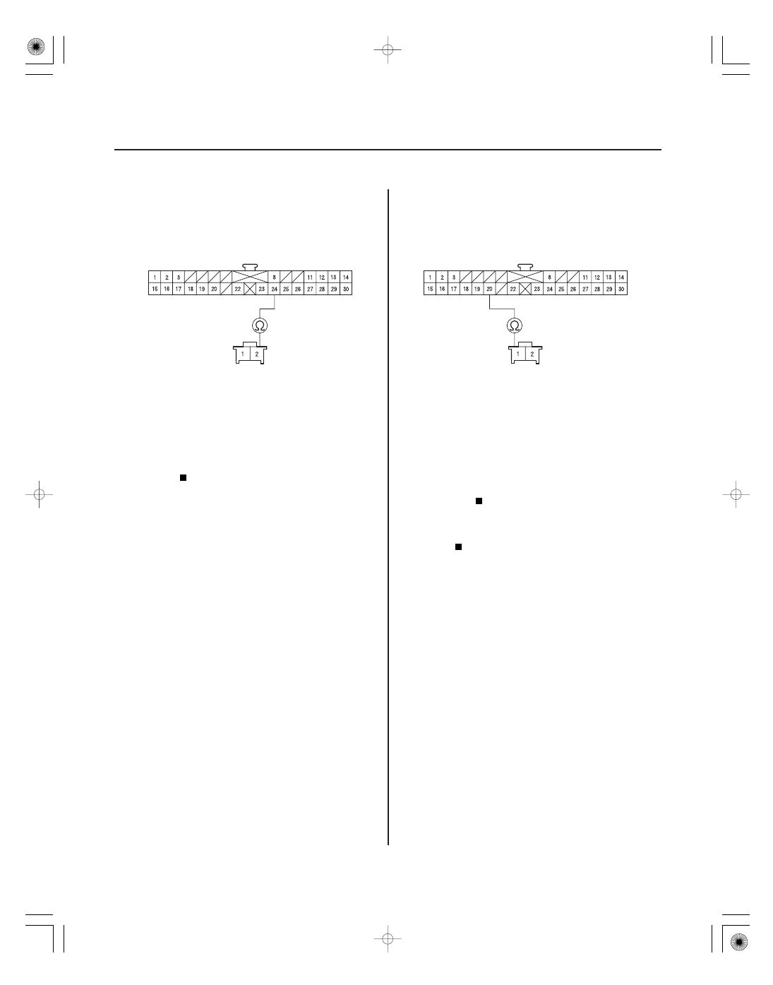
7. Check for continuity between the HVAC control unit

30P connector No. 24 terminal and the evaporator
temperature sensor 2P connector No. 2 terminal.

Go to step 8.

Repair open in the wire between the HVAC

control unit and the evaporator temperature
sensor.

8. Check for continuity between the HVAC control unit

30P connector No. 20 terminal and the evaporator
temperature sensor 2P connector No. 1 terminal.

Check for loose wires or poor connections at

the HVAC control unit 30P connector and at the
evaporator temperature sensor 2P connector. If the
connections are good, substitute a known-good
HVAC control unit, and recheck. If the symptom/
indication goes away, replace the original HVAC
control unit.

Repair open in the wire between the HVAC

control unit and the evaporator temperature
sensor.

Wire side of female terminals

Wire side of female terminals

Wire side of female terminals

Wire side of female terminals

Is ther e continuity?

Is ther e continuity?

01

02

SJC8AH6K733000Y1232FAAT00

DTC B1232 or DTC indicator 8:

YES

NO

YES

NO

YES

NO

YES

NO

21-25

HVAC CONTROL UNIT 30P CONNECTOR

BRN

RED/BLK

HVAC CONTROL UNIT 30P CONNECTOR

BRN

RED/BLK

A Short in the

Evaporator Temperature Sensor Circuit

1. Clear the DTC with the HDS.

2. Operate the heater-A/C control system in several

modes.

3. Check for DTCs using the HDS or self-diagnostic.

Go to step 4.

Intermittent failure.

4. Turn the ignition switch OFF.

5. Remove the evaporator temperature sensor

(see page 21-53) and test it (see page 21-53).

Go to step 6.

Replace the evaporator temperature

sensor.

6. Disconnect the HVAC control unit 30P connector.

7. Check for continuity between body ground and the

HVAC control unit 30P connector No. 20 and No. 24
terminals.

Repair short to body ground in the wires

between the HVAC control unit and the evaporator
temperature sensor.

Go to step 8.

8. Check for continuity between the HVAC control unit

30P connector No. 20 and No. 24 terminals.

Repair short in the wires between the HVAC

control unit and the evaporator temperature
sensor.

Substitute a known-good HVAC control unit,

and recheck. If the symptom/indication goes away,
replace the original HVAC control unit.

Wire side of female terminals

Wire side of female terminals

Is DT C B1232 or 8 indicated?

Is the evapor ator temper atur e sensor OK ?

Is ther e continuity?

Is ther e continuity?

*01

SJC8AH6K733000Y1233FAAT00

DTC B1233 or DTC indicator 1:

YES

NO

YES

NO

YES

NO

21-26

Heating/Air Conditioning

DTC Troubleshooting (cont’d)

GRY

AIR MIX CONTROL MOTOR 7P CONNECTOR

HVAC CONTROL UNIT 30P CONNECTOR

RED/BLK

PNK/BLK

RED/BLK

GRY

PNK/BLK

An Open in

the Air Mix Control Motor Circuit

1. Clear the DTC with the HDS.

2. Operate the heater-A/C control system in several

modes.

3. Check for DTCs using the HDS or self-diagnostic.

Go to step 4.

Intermittent failure, check for loose wires or

poor connections on the air mix control motor
circuit.

4. Turn the ignition switch OFF.

5. Test the air mix control motor (see page 21-55).

Go to step 6.

Replace the air mix control motor (see page

21-55).

6. Disconnect the air mix control motor 7P connector.

7. Disconnect the HVAC control unit 30P connector.

8. Check for continuity between the following

terminals of the HVAC control unit 30P connector
and the air mix control motor 7P connector.
30P:

7P:

No. 20

No. 5

No. 22

No. 7

No. 23

No. 3

Check for loose wires or poor connections at

the HVAC control unit 30P connector and at the air
mix control motor 7P connector. If the connections
are good, substitute a known-good HVAC control
unit and recheck. If the symptom/indication goes
away, replace the original HVAC control unit.

Repair any open in the wires between the

HVAC control unit and the air mix control motor.

Wire side of female terminals

Wire side of female terminals

Is DT C B1233 or 1 indicated?

Is the air mix contr ol motor OK ?

Is ther e continuity?

*01

*02

SJC8AH6K733000Y1234FAAT00

DTC B1234 or DTC indicator 2:

YES

NO

YES

NO

YES

NO

YES

NO

21-27

HVAC CONTROL UNIT 30P CONNECTOR

GRY

PNK/BLK

HVAC CONTROL UNIT 30P CONNECTOR

GRY

PNK/BLK

A Short in the

Air Mix Control Motor Circuit

1. Clear the DTC with the HDS.

2. Operate the heater-A/C control system in several

modes.

3. Check for DTCs using the HDS or self-diagnostic.

Go to step 4.

Intermittent failure.

4. Turn the ignition switch OFF.

5. Test the air mix control motor (see page 21-55).

Go to step 6.

Replace the air mix control motor (see page

21-55).

6. Disconnect the air mix control motor 7P connector.

7. Disconnect the HVAC control unit 30P connector.

8. Check for continuity between body ground and the

HVAC control unit 30P connector No. 22 and No. 23
terminals individually.

Repair any short to body ground in the

wire(s) between the HVAC control unit and the air
mix control motor.

Go to step 9.

9. Check for continuity between the HVAC control unit

30P connector No. 22 and No. 23 terminals.

Repair the short in the wires.

Go to step 10.

(cont’d)

Wire side of female terminals

Wire side of female terminals

Is DT C B1234 or 2 indicated?

Is the air mix contr ol motor OK ?

Is ther e continuity?

Is ther e continuity between any of the ter minals?


Content   ..  395  396  397  398   ..