Honda Ridgeline. Manual - part 394


  Index      Honda     Honda Ridgeline - service repair manual 2006-2008 year


Search            


Content   ..  392  393  394  395   ..


Honda Ridgeline. Manual - part 394


SJC8AH6G24100000000HBAT01
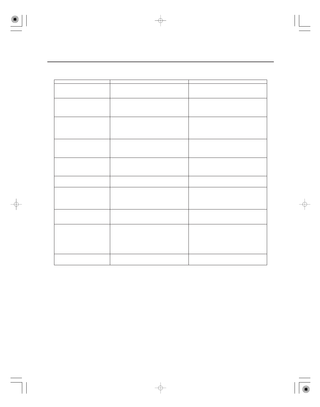
Symptom

Diagnostic procedure

Also check for

21-12

Heating/Air Conditioning

Symptom Troubleshooting Index


Recirculation control doors do not
change between Fresh and
Recirculate

Recirculation control motor circuit
troubleshooting (see page 21-37)

HVAC DTCs (see page 21-8)
Blown fuse No. 30 (7.5 A) in the under-dash
fuse/relay box
Cleanliness and tightness of all terminals

Blower, heater controls, and A/C
do not work

HVAC control power and ground circuit
troubleshooting (see page 21-39)

HVAC DTCs (see page 21-8)
Blown fuse No. 30 (7.5 A) in the under-dash
fuse/relay box
Poor ground at G402 (see page 22-68)
Cleanliness and tightness of all terminals

Both fans do not run at low speed
with the A/C on (but the A/C
compressor runs with the A/C on)

Radiator and A/C condenser fan low speed circuit
troubleshooting (see page 21-40)

HVAC DTCs (see page 21-8)
Blown fuse No. 20 (30 A) in the under-hood
fuse/relay box, and No. 30 (7.5 A) in the under-
dash fuse/relay box
Poor ground at G201 (see page 22-68)
Cleanliness and tightness of all terminals

The A/C condenser fan does not
run at high speed (but both fans
run at low speed and the A/C
compressor operates with the A/C
on)

A/C condenser fan high speed circuit
troubleshooting (see page 21-44)

HVAC DTCs (see page 21-8)
Blown fuse No. 30 (7.5 A) in the under-dash
fuse/relay box
Poor ground at G201 (see page 22-68)
Cleanliness and tightness of all terminals

Both fans do not run at high speed
with the A/C on (but both fans run
at low speed and the A/C
compressor operates with the A/C
on)

Radiator and A/C condenser fan high speed
circuit troubleshooting (see page 21-46)

HVAC DTCs (see page 21-8)
Poor ground at G202 (see page 22-68)
Cleanliness and tightness of all terminals

Both fans run at high speed all the
time with the A/C on

Radiator and A/C condenser fan high speed
circuit troubleshooting (see page 21-46)

HVAC DTCs (see page 21-8)
Poor ground at G202 (see page 22-68)
Cleanliness and tightness of all terminals

The A/C compressor clutch does
not engage (but both fans run with
the A/C on)

A/C compressor clutch circuit troubleshooting
(see page 21-47)

HVAC DTCs (see page 21-8)
Blower motor operation
Blown fuse No. 12 (7.5 A) in the under-hood
fuse/relay box, and No. 30 (7.5 A) in the driver’s
under-dash fuse/relay box
Cleanliness and tightness of all terminals

A/C system does not come on
(both fans and the A/C
compressor do not work); heater
is OK

A/C Pressure switch circuit troubleshooting
(see page 21-49)

Body DTCs in B-CAN System Diagnosis Test
Mode A Troubleshooting (see page 22-99)
HVAC DTCs (see page 21-8)
Cleanliness and tightness of all terminals

Blower fan runs slower than
expected in cold weather

ECT Troubleshooting: ECT sensor 2 circuit low
voltage (see page 11-149), ECT sensor 2 circuit
high voltage (see page 11-151)
NOTE: It is normal for the blower to run slowly
until the engine coolant temperature begins to
rise. If the blower continues to run slowly for an
abnormal length of time, continue to troubleshoot
the problem.

Powertrain DTCs (see page 11-3)
Blower motor operation

HDS does not communicate with
the HVAC control unit or the
vehicle

Troubleshoot the DLC (see page 11-194)

*01

SJC8AH6G24100000000CAAT10

21-13

System Description

EXPANSION VALVE
(Meters the required amount of
refrigerant into the evaporator)

RECEIVER/DRYER
DESICCANT
(Traps debris, and
removes moisture)

A/C COMPRESSOR
(Suction and compression)

A/C CONDENSER
(Radiation of heat)

BLOWER FAN

EVAPORATOR
(Absorption of heat)

EVAPORATOR TEMPERATURE
SENSOR

RELIEF VALVE
(Relieves pressure at the A/C compressor
when the pressure is too high)

HIGH PRESSURE VAPOR

HIGH PRESSURE LIQUID

LOW PRESSURE LIQUID

LOW PRESSURE VAPOR

A/C PRESSURE SWITCH
(Triple function)

The air conditioning system removes heat from the passenger compartment by transferring heat from the ambient air
to the evaporator. The evaporator cools the air with the refrigerant that is circulating through the evaporator. The
refrigerant expands in the evaporator, and the evaporator becomes very cold and absorbs the heat from the ambient
air. The blower fan pushes air across the evaporator where the heat is absorbed, and then it blows the cool air into the
passenger compartment.

This vehicle uses HFC-134a (R-134a) refrigerant, which does not contain chlorofluorocarbons. Pay attention to the
following service items:

• Do not mix refrigerants CFC-12 (R-12) and HFC-134a (R-134a). They are not compatible.
• Use only the recommended polyalkyleneglycol (PAG) refrigerant oil (DENSO ND-OIL 8) designed for the R-134a A/C

compressor. Intermixing the recommended (PAG) refrigerant oil with any other refrigerant oil will result in A/C
compressor failure.

• All A/C system parts (A/C compressor, discharge line, suction line, evaporator, A/C condenser, receiver/dryer,

expansion valve, O-rings for joints) are designed for refrigerant R-134a. Do not exchange with R-12 parts.

• Use a halogen gas leak detector designed for refrigerant R-134a.
• R-12 and R-134a refrigerant servicing equipment are not interchangeable. Use only a recovery/recycling/charging

station that is U.L.-listed and is certified to meet the requirements of SAE J2210 to service the R-134a air
conditioning systems.

• Always recover refrigerant R-134a with an approved recovery/recycling/charging station before disconnecting any

A/C fitting.

(cont’d)

When the refrigerant is below
196 kPa (2.0 kgf/cm , 28 psi)
or above 3,140 kPa (32 kgf/c m,
455 psi), the PCM turns the
compressor relay off to protect
the A/C compressor.
When the refrigerant is above
1,550 kPa (15.5 kgf/ cm, 225 psi),
the A/C pressure sensor
switches the radiator and
A/C condenser fans to
high speed.

2

2

2

02

03

A/C Pressure Switch

21-14

Heating/Air Conditioning

System Description (cont’d)

ON

OFF

196 kPa
(2.0 kgf/cm , 28 psi)

225 kPa
(2.3 kgf/cm , 33 psi)

2,550 kPa
(26.0 kgf/cm , 370 psi)

3,140 kPa
(32.0 kgf/cm , 455 psi)

590 kPa
(6.0 kgf/cm , 86 psi)

29 kPa
(0.3 kgf/cm , 4 psi)

590 kPa (6.0 kgf/cm , 86 psi)

1,520 kPa
(15.5 kgf/cm , 221 psi)

930 kPa
(9.5 kgf/cm , 135 psi)

ON

OFF

HIGH-LOW
PRESSURE
SWITCH

MIDDLE
PRESSURE
SWITCH

2

2

2

2

2

2

2

2

2

The A/C pressure switch consists of a high-low pressure switch (A/C pressure switch A) and a middle pressure switch
(A/C pressure switch B).

• High-low pressure switch

If the refrigerant pressure becomes too high (due to blockage or lack of airflow at the condenser), or too low (due to
leakage), the A/C pressure switch stops the A/C request signal to the PCM and the A/C compressor stops operating.

• Middle pressure switch

If the refrigerant pressure goes above 1,520 kPa (15.5 kgf/cm , 221 psi), the A/C pressure switch closes to signal the
PCM to change the speed of the A/C condenser fan and radiator fan to high. When the refrigerant pressure drops
below 930 kPa (9.5 kgf/cm , 135 psi), the A/C pressure switch opens to signal the PCM to change the speed of the A/C
condenser fan and radiator fan to low.

2

2

04

Heating/Air Conditioning Door Positions

21-15

HOT

COOL

(VENT)

(HEAT/VENT)

(HEAT)

DEFROSTER
DOOR

AIR MIX
DOOR

HEAT/VENT
DOOR

(cont’d)


Content   ..  392  393  394  395   ..