Honda Ridgeline. Manual - part 302
 

  Index      Honda     Honda Ridgeline - service repair manual 2006-2008 year


Search            


Content   ..  300  301  302  303   ..


Honda Ridgeline. Manual - part 302


16

17

18

18-33

Press

07948-SB00101

07965-SD90100

A

B

C

D

E

C
12 x 1.25 mm
74 N·m (7.5 kgf·m, 54 lbf·ft)

A

B

Press

07749-0010000

07746-0010500

07965-SD90100

A

C

B

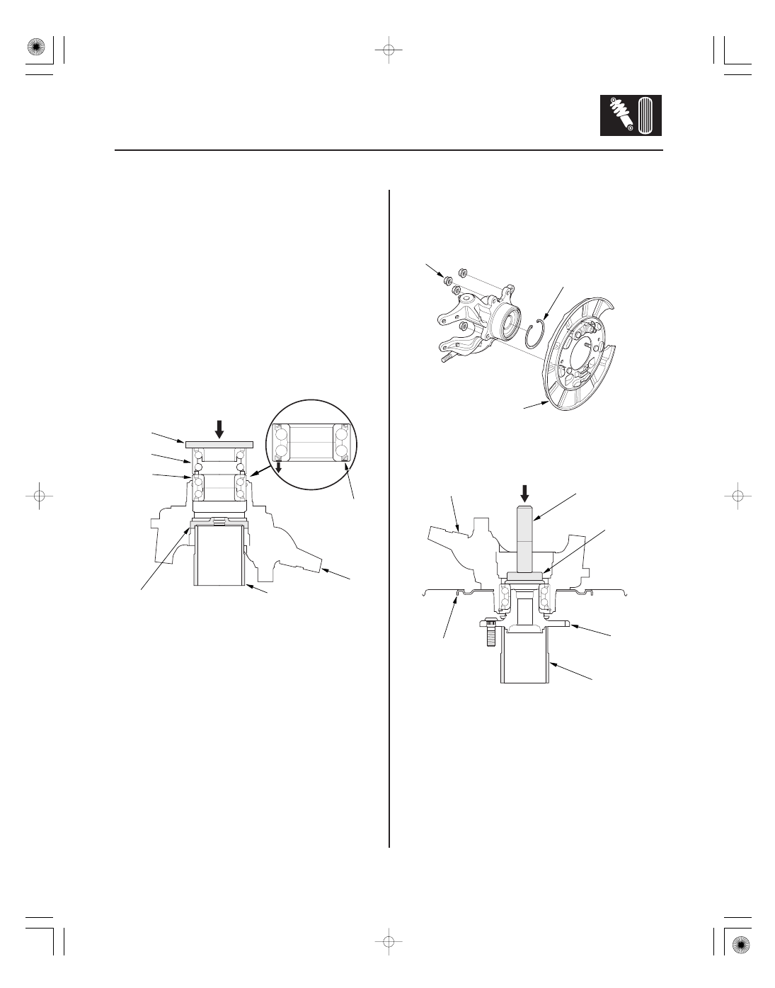
5. Wash the knuckle and hub thoroughly in high flash

point solvent before reassembly.

6. Press a new wheel bearing (A) into the knuckle (B)

using the old bearing (C), a steel plate (D), the
special tools, and a press.

NOTE:

• Install the wheel bearing with the wheel sensor

magnetic encoder (E) (brown color), toward the
inside of the knuckle.

• Remove any oil, grease, dust, metal debris, and

other foreign material from the encoder surface.

• Keep all magnetic tools away from the encoder

surface.

• Be careful not to damage the encoder surface

when you insert the wheel bearing.

7. Install the snap ring (A), backing plate (B), and

flange nuts (C). Tighten the flange nuts to the
specified torque.

8. Install the hub (A) on the knuckle (B) using the

special tools and a hydraulic press. Be careful not
to deform the splash guard (C).

01

02

03

*01

SJC8A00B44100062201KDAT00

Special Tools Required

18-34

Rear Suspension

Upper Arm Removal/Installation

A

B

B

12 x 1.25 mm
49

59 N·m

(5.0

6.0 kgf·m,

36

43 lbf·ft)

07MAC-SL0A102

A

A
12 x 1.25 mm
94 N·m
(9.6 kgf·m,
69 lbf·ft)

B

Ball joint remover, 32 mm 07MAC-SL0A102

1. Raise the rear of the vehicle, and support it with

safety stands in the proper locations (see page
1-10).

2. Remove the rear wheel.

3. Remove the wheel sensor harness clip (A) from the

upper arm (B). Do not disconnect the wheel sensor
connector.

4. Position a floor jack at the connecting point of the

lower arm B and the knuckle.

5. Raise the rear suspension with the floor jack to load

the vehicle weight.

6. Remove the lock pin (A) from the upper arm ball

joint, then remove the nut.

7. Disconnect the upper arm ball joint from the

knuckle using the ball joint remover (see page
18-11).

8. Remove the upper arm mounting bolt (A) and

remove the upper arm (B) from the vehicle.

NOTE: During installation, install the new mounting
bolt.

Replace.

01

*01

SJC8A00B44100037701KDAT01

18-35

18-35

Lower Arm A Removal/Installation

B

D
14 x 1.5 mm
93 N·m
(9.5 kgf·m, 69 lbf·ft)

B
14 x 1.5 mm
101 N·m
(10.3 kgf·m, 74.5 lbf·ft)

A

C

9. Install the upper arm in the reverse order of

removal, and note these items:

• Be careful not to damage the ball joint boot when

installing the knuckle.

• Tighten all mounting hardware to the specified

torque values.

• First install all the components and lightly tighten

the bolts and nuts, then raise the suspension to
load it with the vehicle’s weight before fully
tightening to the specified torque values.

• Torque the castle nut to the lower torque

specification, then tighten it only far enough to
align the slot with the ball joint pin hole. Do not
align the castle nut by loosening it.

• Before installing the wheel, clean the mating

surface of the brake disc and the inside of the
wheel.

• Check the wheel alignment, and adjust it if

necessary (see page 18-5).

1. Raise the rear of the vehicle, and support it with

safety stands in the proper locations (see page
1-10).

2. Remove the rear wheel.

3. Position a floor jack at the connecting point of the

lower arm B and the knuckle.

4. Remove the locknut (B), washer (C), and flange bolt

(D).

NOTE: During installation, install the new locknut
and new mounting bolt.

5. Raise the rear suspension with the floor jack until

you are finished removing the lower arm A.

(cont’d)

Replace.

*02

04

SJC8A00B44100037701KDAT02

18-36

18-36

Rear Suspension

Lower Arm A Removal/Installation
(cont’d)

Lower Arm B Removal/Installation

A
10 x 1.25 mm
49 N·m
(5.0 kgf·m,
36 lbf·ft)

C
18 x 1.5 mm
211 N·m
(21.5 kgf·m, 156 lbf·ft)

D
16 x 1.5 mm
142 N·m
(14.5 kgf·m, 105 lbf·ft)

B

C
12 x 1.25 mm
83 N·m
(8.5 kgf·m,
61 lbf·ft)

A

B

D

6. Install the lower arm A in the reverse order of

removal, and note these items:

• Tighten all mounting hardware to the specified

torque values.

• First install all the components and lightly tighten

the bolts and nuts, then raise the suspension to
load it with the vehicle’s weight before fully
tightening to the specified torque values.

• Before installing the wheel, clean the mating

surface on the brake disc/drum and the inside of
the wheel.

• Check the wheel alignment, and adjust it if

necessary (see page 18-5).

1. Raise the rear of the vehicle, and support it with

safety stands in the proper locations (see page
1-10).

2. Remove the rear wheel.

3. Position a floor jack at the connecting point of

lower arm B and the knuckle.

4. Remove the locknut (A), then remove flange bolt

(C).

NOTE: During installation, install the new locknut
and new flange bolt.

5. Remove the flange bolt (D), and lower the floor jack

gradually.

NOTE: During installation, install the new flange
bolt.

6. Hold the adjusting bolt (A) on the lower arm B, and

remove the self-locking nut (C) and adjusting cam
(D).

7. Remove the adjusting bolt and the lower arm B.

Replace.

Replace.

Replace.


Content   ..  300  301  302  303   ..