Honda Ridgeline. Manual - part 233


  Index      Honda     Honda Ridgeline - service repair manual 2006-2008 year


Search            


Content   ..  231  232  233  234   ..


Honda Ridgeline. Manual - part 233


01

02

03

SJC8A00E10410435145KBAT00

Special Tools Required

14-317

Intermediary Shaft Bearing Replacement

A

07736-A01000B or
07736-A01000A

A

B

07749-0010000

07746-0010400

• Adjustable bearing puller, 25

40 mm

07736-A01000B or 07736-A01000A

• Driver 07749-0010000
• Attachment, 52 x 55 mm 07746-0010400

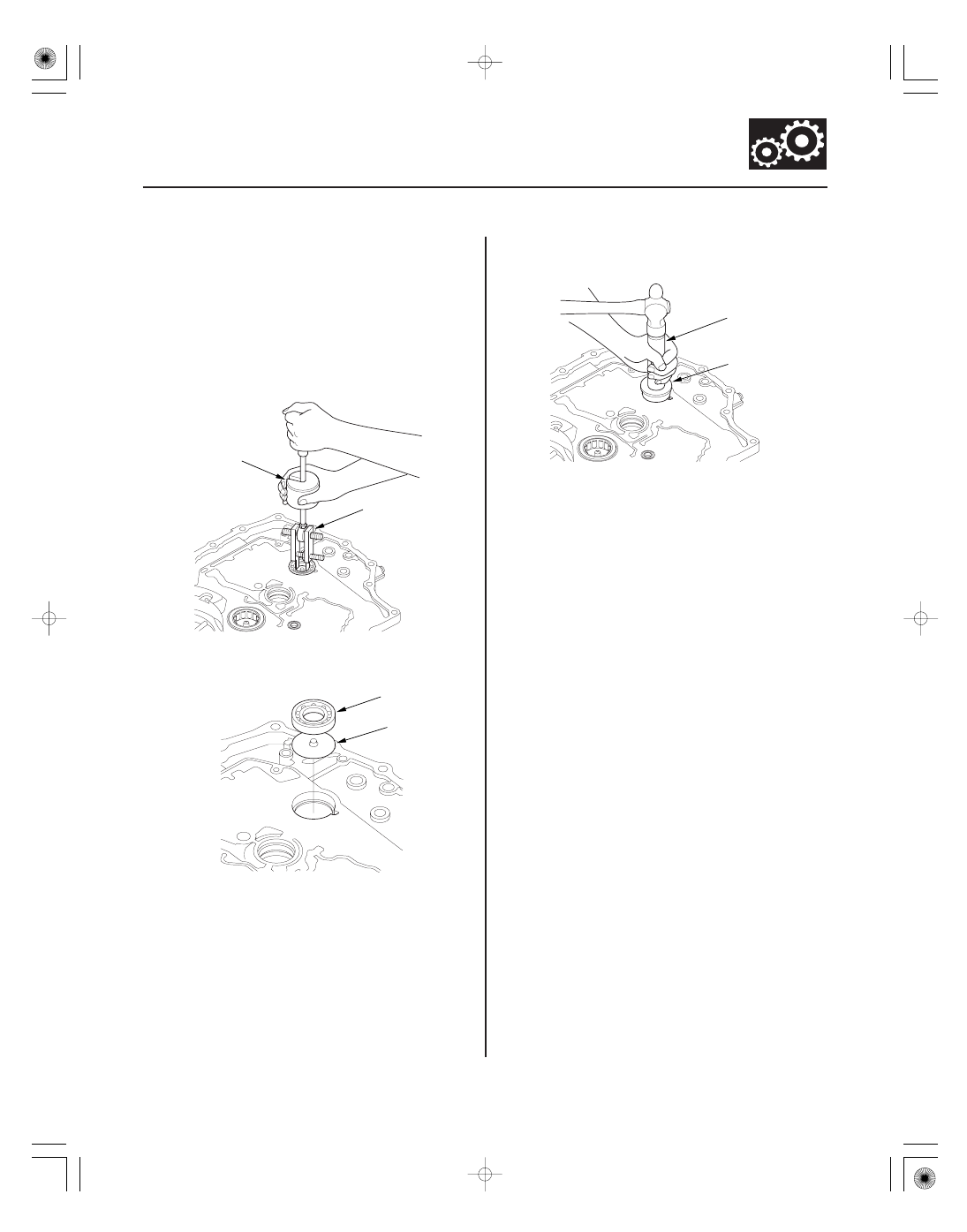
1. Remove the intermediary shaft bearing from the

torque converter housing with the adjustable
bearing puller (25

40 mm), and a commercially

available 3/8 ’’-16 slide hammer (A).

2. Install the ATF guide plate (A), then install the new

bearing (B) in the housing.

3. Drive the bearing into the housing with the driver

and attachment (52 x 55 mm).

03

04

SJC8A00E10400045011KBAT10

Special Tools Required

14-318

Torque Converter Housing

Park Lever Shaft Bearing Replacement

07741-0010201

07936-1660101

07746-0010800

07749-0010000

• Bearing remover shaft set, 12 mm 07936-1660101
• Sliding hammer weight 07741-0010201
• Driver 07749-0010000
• Attachment, 22 x 24 mm 07746-0010800

1. Remove the park lever shaft bearing from the

torque converter housing with the bearing remover
shaft set (12 mm), and sliding hammer weight.

2. Install the new bearing until it bottoms in the

housing with the driver and attachment
(22 x 24 mm).

01

SJC8A00E10411200000MEAT00

14-319

Shafts and Clutches

Mainshaft Disassembly, Inspection, and Reassembly

A

B

C

D

E

F

J

K

I

L

H

G

1. Remove the thrust needle bearing (A), the

mainshaft 5th gear (B), the needle bearing (C), the
thrust needle bearing (D), the mainshaft 5th gear
collar (E), the 4th/5th clutch (F), and the O-rings (G)
from the mainshaft (H).

2. Inspect the condition of the sealing rings (I). If the

sealing rings are worn, distorted, or damaged,
remove the set ring (J) and the needles bearing (K),
and replace the sealing rings with new ones.

3. Inspect the thrust needle bearing and needle

bearing for wear and rough movement.

4. Inspect the splines for excessive wear and damage.

5. Inspect the 4th gear for wear and damage, and

inspect the 4th gear bearing for wear and rough
rotation.

6. Replace the mainshaft 4th gear (L) if the 4th gear is

worn or damaged, or the bearing is worn or
damaged.

7. Check the shaft bearing surfaces for scoring and

excessive wear.

8. Lubricate all parts with ATF during reassembly.

9. Wrap the shaft splines with tape to prevent O-ring

damage, install the new O-rings on the mainshaft,
then remove the tape.

10. Install the 4th/5th clutch.

11. Install the mainshaft 5th gear collar, the thrust

needle bearing, the needle bearing, the mainshaft
5th gear, and the thrust needle bearing.

*01

02

SJC8A00E10411239411KBAT00

Special Tools Required

14-320

Shafts and Clutches

Mainshaft 4th Gear Replacement

A

B

C

07746-0030100

A

B

Driver, 40 mm I.D. 07746-0030100

1. Remove the mainshaft 4th gear (A) with a press.

Place a shaft protector (B) between the press and
mainshaft (C) to prevent damaging the mainshaft.

2. Slide the new mainshaft 4th gear (A) over the

mainshaft (B), then press it into place with the
driver (40 mm I.D.), and the press.


Content   ..  231  232  233  234   ..