Honda Ridgeline. Manual - part 216


  Index      Honda     Honda Ridgeline - service repair manual 2006-2008 year


Search            


Content   ..  214  215  216  217   ..


Honda Ridgeline. Manual - part 216


05

06

07

08

14-249

A

3 N·m
(0.3 kgf·m,
2 lbf·ft)

A

6 x 1.0 mm
9.8 N·m
(1.0 kgf·m, 7.2 lbf·ft)

A

B

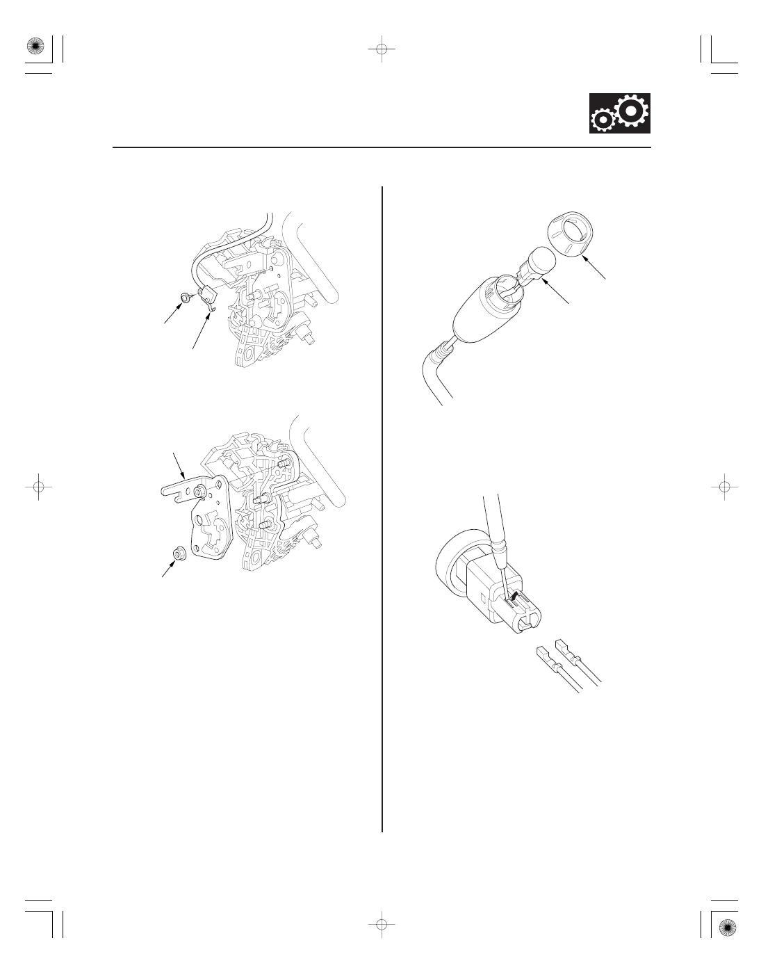
9. Remove the park pin switch (A).

10. Remove the self-locking nuts, and remove the shift

lever position guide (A) from the shift lever bracket.

11. Pry off the shift lever knob ring (A), and remove it.

12. Unlatch the D3 switch harness clamp on the shift

lever bracket, pry out the D3 switch (B), and pull it
from the knob.

13. Remove the D3 switch harness terminals by prying

the lock tabs up with a thin blade screwdriver.

(cont’d)

Replace.

09

10

11

12

14-250

Automatic Transmission

Shift Lever Bracket Assembly Replacement (cont’d)

A

14. Pull the D3 switch harness wires gently from shift

lever bracket side, and remove the harness wires
and tube. Remove the D3 switch harness clamp (A).

15. Remove the shift lever knob from the shift lever.

16. Replace the shift lever bracket.

17. Install the shift lever knob on a new shift lever.

18. Apply silicone grease to the opening detent of the

shift lever position guide, and install the shift lever
position guide with new self-locking nuts on the
shift lever bracket.

19. Shift the shift lever into P.

20. Insert a wire into the shift lever end, pass it through

the shift lever, then pull the wire out.

21. Wrap the D3 switch terminals with tape, and tie a

string around the switch terminals.

22. Pull the wire from the shift lever end, and pull the

D3 switch harness terminals out of the shift lever
end.

23. Remove the wire and tape.

24. Install the D3 switch harness terminals in the D3

switch. Either harness terminal can be installed in
either cavity.

13

14

14-251

C

B

A

A

B

C

D

E

E

25. Install the D3 switch (A) in the shift lever knob (B).

26. Install the shift lever knob ring (C).

27. Insert the D3 switch harness wires (connector side)

through the shift lever into the hole behind the shift
lock solenoid.

28. Install the park pin switch by aligning the tab with

the positioning hole on the shift lever position
guide. Apply non-hardening thread lock sealant to
the screw, then secure the park pin switch with the
screw.

29. Apply silicone grease to the pin on the shift lever

bracket, and install the shift lock stop over the pin.

30. Install the shift lock solenoid plunger and the

plunger spring in the shift lock solenoid.

31. Apply silicone grease to the tip of the shift lock stop,

and install the shift lock solenoid by aligning the
joint of the shift lock solenoid plunger with the tip
of the shift lock stop.

32. Apply silicone grease to the shift lock release pin

and spring, and install the shift lock release, spring,
and pin.

33. Apply silicone grease to the sliding areas between

the shift lever link and the shift lever bracket.

34. Apply silicone grease to the shift lever link bushing,

and install the bushing in the shift lever link.

35. Install the shift lever link with installing the shift

lever pin into the shift lever link bushing.

36. Apply silicone grease to seating area of the washer

on the shift lever link, and install the washer and
the new self-locking nut.

37. Install the RED harness terminal (A) of the shift lock

solenoid in the No. 5 cavity, and the BLK harness
terminal (B) in the No. 6 cavity.

38. Install the D3 switch harness terminals (WHT) (C) in

the No. 3 and No. 4 cavities. Either D3 switch
harness terminal can be installed in the No. 3 and
No. 4 cavities.

39. Install the park pin switch harness terminals (BLK)

(D) in the No. 1 and No. 2 cavities. Either park pin
switch harness terminal can be installed in the
No. 1 and No. 2 cavities.

40. Make sure that all six terminals lock securely, then

install the lock covers (E) securely in place.

(cont’d)

Terminal side of male terminals

15

16

14-252

Automatic Transmission

Shift Lever Bracket Assembly Replacement (cont’d)

A

B

C

A

B

C

D

E

B

41. Install the D3 switch harness clamp (A), then install

the harness (B) in the clamp at the mark (C).

42. Route the harnesses (A) through the guides (B).

43. Align the marks (C) on each harness, and tie the

harness together into bundle with a new harness
clamp (D) over the marks.

44. Tie the harness together into bundle with a new

harness clamp, then install the harness clamp (E)
on the shift lever bracket.

45. Install the shift lever assembly (see page 14-245).


Content   ..  214  215  216  217   ..