Honda Ridgeline. Manual - part 209


  Index      Honda     Honda Ridgeline - service repair manual 2006-2008 year


Search            


Content   ..  207  208  209  210   ..


Honda Ridgeline. Manual - part 209


11

12

13

14

14-221

C

D

B

A

A

B

C

D

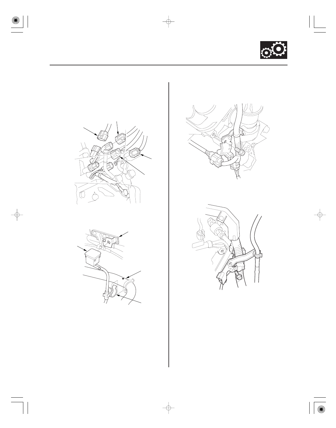
30. Disconnect the input shaft (mainshaft) speed

sensor connector (A), the output shaft
(countershaft) speed sensor connector (B), the ATF
temperature sensor connector (C), and the 3rd
clutch transmission fluid pressure switch connector
(D).

31. Remove the transfer breather (A) from the throttle

cable bracket (B), and remove the transfer breather
hose clamp (C) from the heater hose (D).

32. Remove the connector bracket from the engine

front cylinder head; use the bracket bolt hole to
attach the engine hanger balancer bar front arm.

33. Remove the harness clamp bracket from the engine

rear cylinder head; use the bracket bolt hole to
attach the engine hanger balancer bar rear arm.

(cont’d)

40

41

16

17

14-222

Automatic Transmission

Transmission Removal (cont’d)

A

A

B

VSB02C000024

VSB02C000019

AAR-T-12566

A

C

B

34. Remove the service caps (A) for the front damper

flange nuts from the cowl cover (B). Position the
engine hanger adapters (VSB02C000024) with the
‘‘FRONT’’ mark facing forward over the damper
flange nuts.

35. Install the engine balance bar (VSB02C000019);

attach the front arm (A) to the front cylinder head
with a spacer and the 10 mm bolt, and attach the
rear arm (B) to the rear cylinder head with the
8 mm bolt.

36. Install the engine support hanger (AAR-T-12566) to

the vehicle, and attach the hook to slotted hold in
the engine balance bar. Tighten the wing nut (C) by
hand, and to lift and support the engine.

37. Remove the front mount nut.

38. Remove the front subframe stiffener.

18

19

20

21

14-223

A

B

A

B

C

D

F

G

E

H

K

J

I

A

B

C

B

C

A

39. Remove exhaust pipe A and its mount (B).

40. Remove the lock pins (A) and the castle nuts (B),

and separate the lower arms (C) from the knuckles
(D) (see page 18-12).

41. Insert a 6 mm Allen wrench (E) in the top of the ball

joint pin (F), and remove the nuts (G), then separate
the stabilizer link (H).

42. Remove the cotter pins (I) and nuts (J), and

separate the tie-rod end ball joints (K) from the
knuckles (see step 9 on page 18-15).

43. Remove the bolt securing the transfer breather

hose bracket (A), and disconnect the breather hose
(B) from the breather pipe (C) on the transfer
assembly.

44. Make a reference mark (A) across the propeller

shaft (B) and the transfer companion flange (C).

45. Separate the propeller shaft from the transfer

companion flange.

(cont’d)

22

23

24

25

14-224

Automatic Transmission

Transmission Removal (cont’d)

B

A

A

B

C

46. Remove the transfer assembly from the

transmission.

47. Remove the torque converter cover (A), and

remove the drive plate bolts (B) (8) while rotating
the crankshaft pulley.

48. Disconnect the power steering pressure switch

connector.

49. Remove the power steering fluid hose (A) from the

hose clamp (B) at the right front of the subframe.

50. Loosen the hose clamp bolt, then disconnect the

power steering fluid hose from the fluid line (C).


Content   ..  207  208  209  210   ..