Honda Ridgeline. Manual - part 61


  Index      Honda     Honda Ridgeline - service repair manual 2006-2008 year


Search            


Content   ..  59  60  61  62   ..


Honda Ridgeline. Manual - part 61


*04

Substituting the PCM

Special Tools Required

11-8

Fuel and Emissions Systems

General Troubleshooting Information (cont’d)

A

7. If the software in the PCM is the latest, disconnect

the HDS/HIM from the DLC, and go back to the
procedure that you were doing. If the software in
the PCM is not the latest, follow the instructions on
the screen. If prompted to choose the PGM-FI
system or the A/T system, make sure you update
both.

NOTE: If the PCM update system requires you to
cool the PCM, follow the screen prompts. If you run
into a problem (programming takes over
15 minutes, status bar goes over 100 %, D or
immobilizer light flashes, HDS tablet freezes, etc.)
during the update procedure, follow these steps to
minimize the chance of damaging the PCM:

• Leave the ignition switch in the ‘‘ON (II)’’ position.
• Connect a jumper battery (do not connect a

battery charger).

• Shut down the HDS.
• Disconnect the HDS from the DLC.
• Reboot the HDS.
• Reconnect the HDS to the DLC, and try the

update procedure again.

8. If the TP POSITION CHECK failed in step 6, clean

the throttle body (see page 11-314).

9. Do the PCM idle learn procedure (see page 11-273).

10. Do the crank (CKP) pattern learn procedure.

• Honda diagnostic system (HDS) tablet tester
• Honda interface module (HIM) and an iN workstation

with HDS and CM update software

• HDS pocket tester
• GNA-600 and an iN workstation with HDS and CM

update software

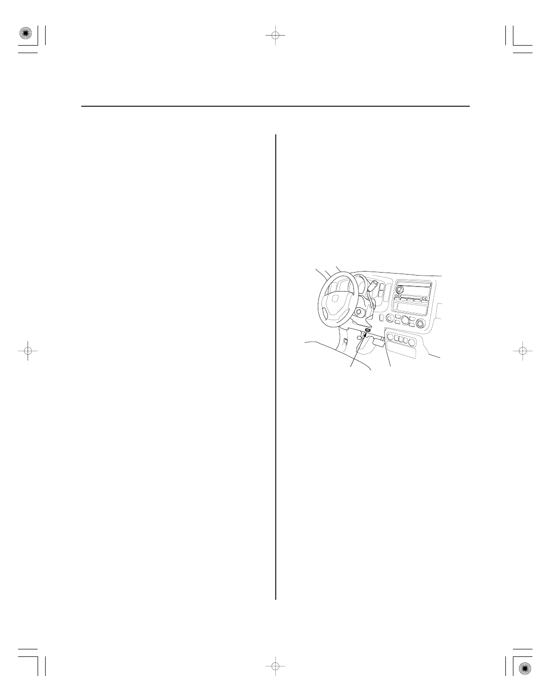
NOTE: Use this procedure when you have to substitute
a known-good PCM during troubleshooting procedures.

1. Connect the HDS to the data link connector (DLC)

(A) located under the driver’s side of the dashboard.

2. Turn the ignition switch ON (II).

3. Make sure the HDS communicates with the PCM

and other vehicle systems. If it doesn’t, go to the
DLC circuit troubleshooting (see page 11-194). If
you are returning from DLC circuit troubleshooting,
skip step 4 to 8, then clean the throttle body after
substituting the PCM (see page 11-314).

4. Select the INSPECTION MENU with the HDS.

5. Select the ETCS TEST, then select the TP POSITION

CHECK, and follow the screen prompts.

NOTE: If the TP POSITION CHECK indicates FAILED,
continue this procedure.

6. Jump the SCS line with the HDS.

21

OBD Status

11-9

E
9.8 N·m (1.0 kgf·m, 7.2 lbf·ft)

A

D

F

B

C

7. Remove the cover (D).

8. Disconnect PCM connectors A, B, and C.

NOTE: PCM connectors A, B, and C have symbols
(A=

, B=

, C=

) embosed on them for

identification.

9. Remove the bolts (E), then remove the PCM (F).

10. Install the parts in the reverse order of removal.

11. Open the SCS with the HDS.

12. Turn the ignition switch ON (II).

NOTE: DTC P0630 ‘‘VIN Not Programmed or
Mismatch’’ may be stored because the VIN has not
been programmed into the PCM; ignore it, and
continue this procedure.

13. Manually input the VIN to the PCM with the HDS.

14. Update the PCM if it does not have the latest

software.

15. Select the IMMOBI SYSTEM with the HDS.

16. Enter the immobilizer code with the PCM

replacement procedure in the HDS; it allows you to
start the engine.

17. Reset the PCM with the HDS.

18. If the TP POSITION CHECK failed in step 6, clean

the throttle body (see page 11-314).

19. Do the PCM idle learn procedure (see page 11-273).

20. Do the crank (CKP) pattern learn procedure.

The OBD status shows the current system status of
each DTC and all of the parameters. This function is
used to see if the repair was successfully completed.
The results of diagnostic tests for the DTC are displayed
as:

• PASSED: The on board diagnosis is successfully

finished.

• FAILED: The on board diagnosis has finished but

failed.

• EXECUTING: The vehicle is in enable criteria

conditions for the DTC and the on board diagnosis is
running.

• NOT COMPLETED: The on board diagnosis was

running but is out of the enable conditions of the DTC.

• OUT OF CONDITION: The vehicle has stayed out of

the enable conditions for the DTC.

―――
―――

―――
―――

―――
―――
―――
―――


―――

―――

―――

―――

―――

―――

―――

―――


―――
―――


―――

SJC8A00A20300000000GAAT00

DTC

Detection Item

MIL

Note

(MIL indication )

1

Two Drive Cycle

Detection

11-10

Fuel and Emissions Systems

DTC Troubleshooting Index

P0107 (3)

Manifold Absolute Pressure (MAP) Sensor Circuit Low Voltage

ON

(see page 11-59)

P0108 (3)

Manifold Absolute Pressure (MAP) Sensor Circuit High Voltage

ON

(see page 11-61)

P0111 (10)

Intake Air Temperature (IAT) Sensor Circuit Range/Performance Problem

ON

(see page 11-64)

P0112 (10)

Intake Air Temperature (IAT) Sensor Circuit Low Voltage

ON

(see page 11-65)

P0113 (10)

Intake Air Temperature (IAT) Sensor Circuit High Voltage

ON

(see page 11-67)

P0116 (86)

Engine Coolant Temperature (ECT) Sensor 1 Circuit Range/Performance
Problem

ON

(see page 11-70)

P0117 (6)

Engine Coolant Temperature (ECT) Sensor 1 Circuit Low Voltage

ON

(see page 11-71)

P0118 (6)

Engine Coolant Temperature (ECT) Sensor 1 Circuit High Voltage

ON

(see page 11-73)

P0122 (7)

Throttle Position (TP) Sensor A Circuit Low Voltage

ON

(see page 11-208)

P0123 (7)

Throttle Position (TP) Sensor A Circuit High Voltage

ON

(see page 11-210)

P0125 (86)

Engine Coolant Temperature (ECT) Sensor 1 Malfunction/Slow Response

ON

(see page 11-76)

P0128 (87)

Cooling System Malfunction

ON

(see page 11-77)

P0133 (157)

Rear Air Fuel Ratio (A/F) Sensor (Bank 1, Sensor 1) Circuit Slow Response

ON

(see page 11-79)

P0134 (151)

Rear Air Fuel Ratio (A/F) Sensor (Bank 1, Sensor 1) Heater System
Malfunction

ON

(see page 11-80)

P0135 (151)

Rear Air Fuel Ratio (A/F) Sensor (Bank 1, Sensor 1) Heater Circuit
Malfunction

ON

(see page 11-81)

P0137 (161)

Rear Secondary Heated Oxygen Sensor (Secondary HO2S (Bank 1,
Sensor 2)) Circuit Low Voltage

ON

(see page 11-86)

P0138 (161)

Rear Secondary Heated Oxygen Sensor (Secondary HO2S (Bank 1,
Sensor 2)) Circuit High Voltage

ON

(see page 11-88)

P0139 (161)

Rear Secondary Heated Oxygen Sensor (Secondary HO2S (Bank 1,
Sensor 2)) Circuit Slow Response

ON

(see page 11-91)

P0141 (163)

Rear Secondary Heated Oxygen Sensor (Secondary HO2S (Bank 1,
Sensor 2)) Heater Circuit Malfunction

ON

(see page 11-92)

P0153 (158)

Front Air Fuel Ratio (A/F) Sensor (Bank 2, Sensor 1) Circuit Slow
Response

ON

(see page 11-79)

P0154 (152)

Front Air Fuel Ratio (A/F) Sensor (Bank 2, Sensor 1) Heater System
Malfunction

ON

(see page 11-80)

P0155 (152)

Front Air Fuel Ratio (A/F) Sensor (Bank 2, Sensor 1) Heater Circuit
Malfunction

ON

(see page 11-81)

P0157 (162)

Front Secondary Heated Oxygen Sensor (Secondary HO2S (Bank 2,
Sensor 2)) Circuit Low Voltage

ON

(see page 11-86)

P0158 (162)

Front Secondary Heated Oxygen Sensor (Secondary HO2S (Bank 2,
Sensor 2)) Circuit High Voltage

ON

(see page 11-88)

P0159 (162)

Front Secondary Heated Oxygen Sensor (Secondary HO2S (Bank 2,
Sensor 2)) Circuit Slow Response

ON

(see page 11-91)

P0161 (164)

Front Secondary Heated Oxygen Sensor (Secondary HO2S (Bank 2,
Sensor 2)) Heater Circuit Malfunction

ON

(see page 11-92)

P0171 (153)

Rear Bank (Bank 1) Fuel System Too Lean

ON

(see page 11-96)

P0172 (153)

Rear Bank (Bank 1) Fuel System Too Rich

ON

(see page 11-96)

P0174 (154)

Front Bank (Bank 2) Fuel System Too Lean

ON

(see page 11-96)

P0175 (154)

Front Bank (Bank 2) Fuel System Too Rich

ON

(see page 11-96)

P0222 (7)

Throttle Position (TP) Sensor B Circuit Low Voltage

ON

(see page 11-213)

P0223 (7)

Throttle Position (TP) Sensor B Circuit High Voltage

ON

(see page 11-215)

P0300 (77) and
some of
P0301 (71)
P0302 (72)
P0303 (73)
P0304 (74)
P0305 (75)
P0306 (76)

Random Misfire Detected

ON

(see page 11-98)

P0301 (71)

No. 1 Cylinder Misfire Detected

ON

(see page 11-101)

P0302 (72)

No. 2 Cylinder Misfire Detected

ON

(see page 11-101)

P0303 (73)

No. 3 Cylinder Misfire Detected

ON

(see page 11-101)

P0304 (74)

No. 4 Cylinder Misfire Detected

ON

(see page 11-101)

P0305 (75)

No. 5 Cylinder Misfire Detected

ON

(see page 11-101)

P0306 (76)

No. 6 Cylinder Misfire Detected

ON

(see page 11-101)

P0325 (23)

Knock Sensor Circuit Malfunction

ON

(see page 11-110)

NOTE: The above DTCs are indicated when the PGM-FI system is selected in the HDS.
Some automatic transmission DTCs cause the MIL to come on. If the MIL is on and no DTCs are indicated in the PGM-FI system, select the A/T
system, and check for automatic transmission DTCs.

1: These DTCs are indicated by a blinking MIL when the SCS line is jumped with the HDS.

―――
―――
―――
―――
―――
―――


―――


―――

―――
―――


―――

―――
―――


―――

―――


―――
―――

―――
―――

―――
―――
―――
―――

―――
―――

DTC

Detection Item

MIL

Note

(MIL indication )

1

Two Drive Cycle

Detection

11-11

P0335 (4)

Crankshaft Position (CKP) Sensor A No Signal

ON

(see page 11-113)

P0339 (4)

Crankshaft Position (CKP) Sensor A Intermittent Interruption

ON

(see page 11-116)

P0340 (9)

Camshaft Position (CMP) Sensor No Signal

ON

(see page 11-117)

P0344 (9)

Camshaft Position (CMP) Sensor Intermittent Interruption

ON

(see page 11-120)

P0385 (54)

Crankshaft Position (CKP) Sensor B No Signal

ON

(see page 11-113)

P0389 (54)

Crankshaft Position (CKP) Sensor B Intermittent Interruption

ON

(see page 11-116)

P0401 (80)

Exhaust Gas Recirculation (EGR) Insufficient Flow

ON

(see page 11-328)

P0404 (12)

Exhaust Gas Recirculation (EGR) Control Circuit Range/Performance
Problem

ON

(see page 11-330)

P0406 (12)

Exhaust Gas Recirculation (EGR) Valve Position Sensor Circuit High
Voltage

ON

(see page 11-333)

P0420 (165)

Rear Bank Catalyst System Efficiency Below Threshold (Bank 1)

ON

(see page 11-323)

P0430 (166)

Front Bank Catalyst System Efficiency Below Threshold (Bank 2)

ON

(see page 11-323)

P0443 (92)

Evaporative Emission (EVAP) Canister Purge Valve Circuit Malfunction

ON

(see page 11-347)

P0451 (91)

Fuel Tank Pressure (FTP) Sensor Circuit Range/Performance Problem

ON

(see page 11-351)

P0452 (91)

Fuel Tank Pressure (FTP) Sensor Circuit Low Voltage

ON

(see page 11-352)

P0453 (91)

Fuel Tank Pressure (FTP) Sensor Circuit High Voltage

ON

(see page 11-355)

P0455 (90)

Evaporative Emission (EVAP) System Very Large Leak Detected

ON

(see page 11-358)

P0456 (90)

Evaporative Emission (EVAP) System Very Small Leak Detected

ON

(see page 11-358)

P0457 (90)

Evaporative Emission (EVAP) System Leak Detected/Fuel Fill Cap Loose
or Missing

ON

(see page 11-361)

P0461 (121)

Fuel Level Sensor (Fuel Gauge Sending Unit) Circuit Range/Performance
Problem

OFF

(see page 11-276)

P0462 (121)

Fuel Level Sensor (Fuel Gauge Sending Unit) Circuit Low Voltage

OFF

(see page 11-277)

P0463 (121)

Fuel Level Sensor (Fuel Gauge Sending Unit) Circuit High Voltage

OFF

(see page 11-279)

P0496 (92)

Evaporative Emission (EVAP) System High Purge Flow

ON

(see page 11-363)

P0497 (90)

Evaporative Emission (EVAP) System Low Purge Flow

ON

(see page 11-364)

P0498 (117)

Evaporative Emission (EVAP) Canister Vent Shut Valve Control Circuit
Low Voltage

ON

(see page 11-367)

P0499 (117)

Evaporative Emission (EVAP) Canister Vent Shut Valve Control Circuit
High Voltage

ON

(see page 11-370)

P0506 (14)

Idle Control System RPM Lower than Expected

ON

(see page 11-263)

P0507 (14)

Idle Control System RPM Higher than Expected

ON

(see page 11-265)

P0562 (34)

Charging System Low Voltage

OFF

(see page 11-121)

P0563 (34)

Powertrain Control Module (PCM) Power Source Circuit Unexpected
Voltage

OFF

(see page 11-122)

P0602 (196)

Powertrain Control Module (PCM) Programming Error

OFF

(see page 11-125)

P0603 (131)

Powertrain Control Module (PCM) Internal Circuit Malfunction (Keep Alive
Memory (KAM) Error)

ON

(see page 11-125)

P0607 (131)

Lost Communication with Electronic Throttle Control System (ETCS)

ON

(see page 11-217)

P061F (132)

Electronic Throttle Control System (ETCS) Malfunction

ON

(see page 11-218)

P0630 (139)

VIN Not Programmed or Mismatch

ON

(see page 11-126)

P0641 (133)

Sensor Reference Voltage A Malfunction

ON

(see page 11-127)

P0685 (135)

Powertrain Control Module (PCM) Power Control Circuit/Internal Circuit
Malfunction

ON

(see page 11-130)

P0700 (70)

ON

(see page 11-131)

P0700 (70)

OFF

(see page 11-131)

NOTE: The above DTCs are indicated when the PGM-FI system is selected in the HDS.
Some automatic transmission DTCs cause the MIL to come on. If the MIL is on and no DTCs are indicated in the PGM-FI system, select the A/T
system, and check for automatic transmission DTCs.

1: These DTCs are indicated by a blinking MIL when the SCS line is jumped with the HDS.
2: The D indicator and the MIL may come on at the same time.

(cont’d)

2

Automatic Transmission (A/T) Control System Malfunction

Automatic Transmission (A/T) Control System Malfunction


Content   ..  59  60  61  62   ..