Honda Ridgeline. Manual - part 41
 

  Index      Honda     Honda Ridgeline - service repair manual 2006-2008 year


Search            


Content   ..  39  40  41  42   ..


Honda Ridgeline. Manual - part 41


04

06

6-51

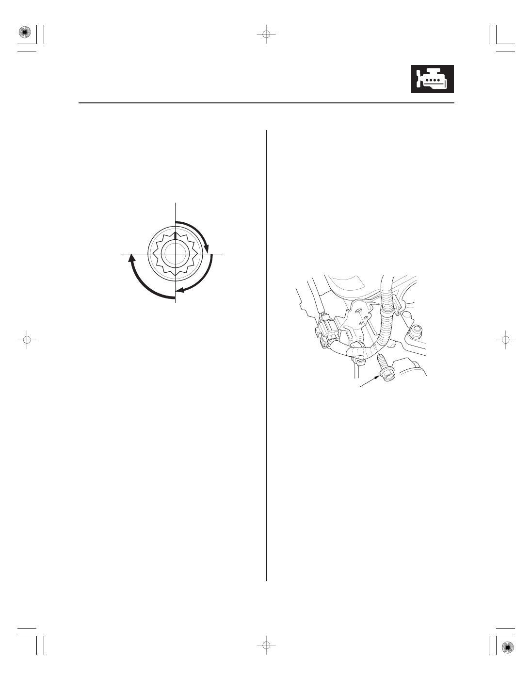
FIRST STEP

SECOND STEP

THIRD STEP
(New bolt)

10 x 1.25 mm
44 N·m
(4.5 kgf·m, 33 lbf·ft)

15. After torquing, tighten all cylinder head bolts in two

steps (90 ° per step). If you are using a new cylinder
head bolt, tighten the bolt an extra 90 °.

NOTE: Remove the cylinder head bolt if you
tightened it beyond the specified angle, and go
back to step 11 of the procedure. Do not loosen it
back to the specified angle.

16. Install the timing belt (see page 6-16).

17. Adjust the valve clearance (see page 6-8).

18. Install the cylinder head covers (see page 6-26).

19. Install the water passage (see page 10-9).

20. Install the front warm up three way catalytic

converter (front WU-TWC) (see page 11-325) and
rear warm up three way catalytic converter (rear
WU-TWC) (see page 11-326).

21. Install the fuel rails (see page 11-197).

22. Install the connector bracket to the front cylinder

head.

(cont’d)

07

08

09

*02

6-52

Cylinder Head

Cylinder Head Installation (cont’d)

8 x 1.25 mm
22 N·m
(2.2 kgf·m, 16 lbf·ft)

A

B

6 x 1.0 mm
12 N·m
(1.2 kgf·m, 8.7 lbf·ft)

B

A

23. Install the harness clamp bracket to the rear

cylinder head.

24. Install the upper radiator hose (A) and lower

radiator hose (B).

25. Install the purge joint.

26. Connect the fuel feed hose (A) (see page 11-295),

then install the quick-connect fitting cover (B).

11

6-53

8 x 1.25 mm
22 N·m
(2.2 kgf·m, 16 lbf·ft)

6 x 1.0 mm
12 N·m (1.2 kgf·m, 8.7 lbf·ft)

A

B

27. Connect the engine wire harness connectors, and

install the wire harness clamps to the cylinder head.

• Six injector connectors
• Engine coolant temperature (ECT) sensor 1

connector

• Engine coolant temperature (ECT) sensor 2

connector

• Crankshaft position (CKP) sensor connector
• Exhaust gas recirculation (EGR) valve connector
• Rocker arm oil control solenoid (VTEC solenoid

valve) connector

• Rocker arm oil pressure switch (VTEC oil

pressure switch) connector

• Oil pressure switch connector
• Two air fuel ratio (A/F) sensor connectors
• Two secondary heated oxygen sensor

(secondary HO2S) connectors

28. Install the intake manifold (see page 9-5).

29. Install the alternator (see page 4-35).

30. Install the power steering (P/S) pump (A) and P/S

hose bracket (B).

31. Install the drive belt (see page 4-31).

32. Clean the battery posts and cable terminals, then

assemble them and apply grease to prevent
corrosion.

33. After installation, check that all tubes, hoses, and

connectors are installed correctly.

34. Inspect for fuel leaks. Turn the ignition switch

ON (II) (do not operate the starter) so the fuel pump
runs for about 2 seconds and pressurizes the fuel
line. Repeat this operation three times, then check
for fuel leakage at any point in the fuel line.

35. Refill the radiator with engine coolant, and bleed

air from the cooling system with the heater valve
open (see step 9 on page 10-7).

36. Do the crankshaft position (CKP) pattern clear/CKP

pattern learn procedure (see page 11-4).

37. Do the power window control unit reset procedure

(see page 22-209).

38. Inspect the idle speed (see page 11-272).

39. Inspect the ignition timing (see page 4-18).

40. Enter the anti-theft codes for the audio system and

navigation system (if equipped).

41. Set the clock (on vehicles without navigation).

01

SJC8A00A14616716021KCAT01

01

02

SJC8A00A14600017841KCAT02

Special Tools Required

Front:

Rear:

6-54

6-54

Cylinder Head

Camshaft Oil Seal Installation - In
Car

Sealing Bolt Installation

C

A
07PAF-0030100

B

D

A
28 x 1.5 mm
78 N·m
(8.0 kgf·m, 58 lbf·ft)

B

A
16 x 1.5 mm
39 N·m
(4.0 kgf·m, 29 lbf·ft)

A
28 x 1.5 mm
78 N·m
(8.0 kgf·m, 58 lbf·ft)

B

Camshaft oil seal driver 07PAF-0030100

1. Remove the timing belt (see page 6-13).

2. Remove the camshaft pulley and back cover (see

step 20 on page 6-30).

3. Remove the camshaft oil seal.

4. Dry the camshaft oil seal housing.

5. Apply a light coat of multipurpose grease to the lip

of the camshaft oil seal.

6. Using the special tool (A), washer (B), and a 12 x 75

x 1.25 mm bolt (C), press in the camshaft oil seal
(D) about 0.5

1.5 mm (0.02

0.06 in.) below the

surface of the cylinder head.

7. Apply new engine oil to the threads of the camshaft

pulley mounting bolt. Install the back cover, then
install the camshaft pulley (see step 11 on page
6-48).

8. Install the timing belt (see page 6-16).

NOTE: When installing the sealing bolt (A), always use
a new washer (B).

Replace.

Replace.


Content   ..  39  40  41  42   ..