Honda Element. Manual - part 252
 

  Index      Honda     Honda Element - service repair manual 2007-2008 year


Search            


Content   ..  250  251  252  253   ..


Honda Element. Manual - part 252


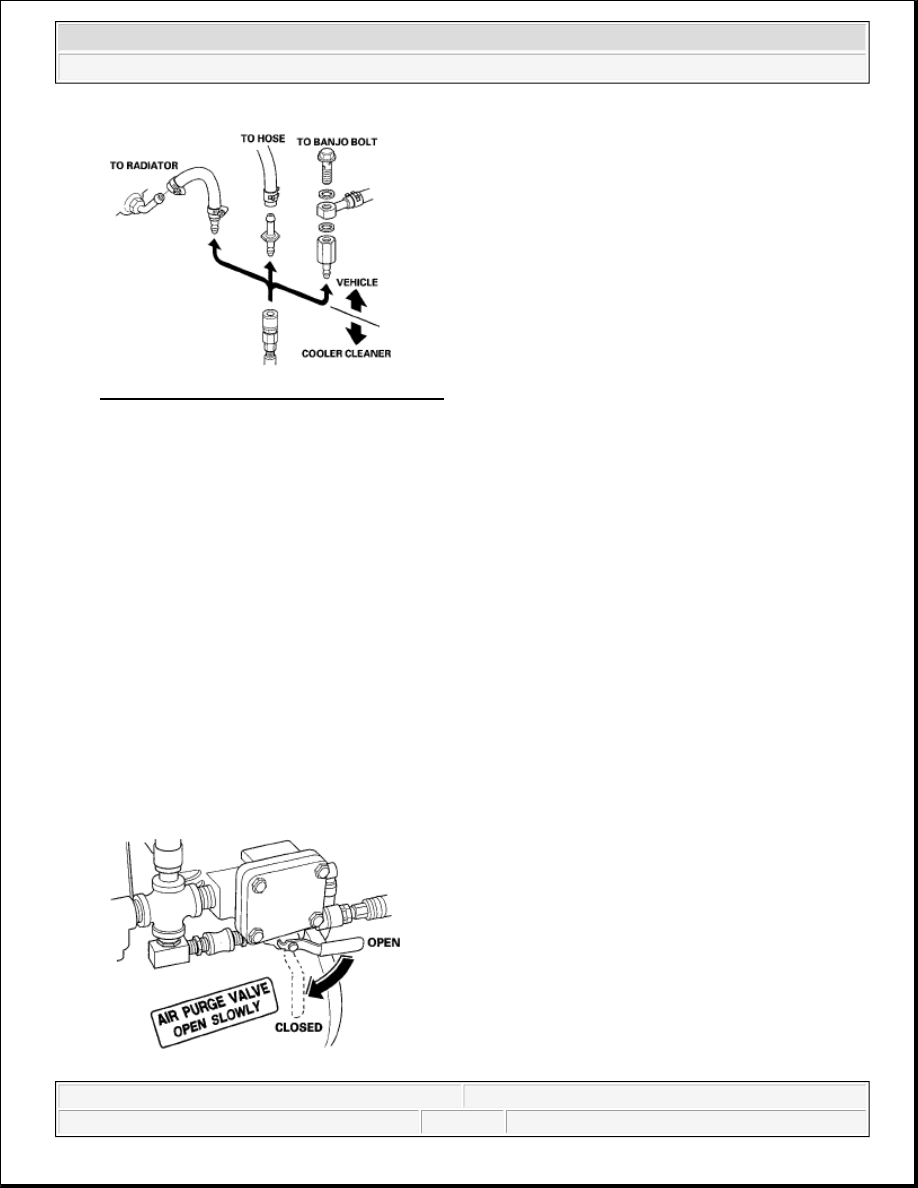
Fig. 276: Identifying Radiator Hoses Fittings 
Courtesy of AMERICAN HONDA MOTOR CO., INC. 

5. Connect the red hose to the cooler outlet line (the line that normally goes to the external filter on the 

transmission).  

6. Connect the blue hose to the cooler inlet line.  

7. Connect a shop air hose (regulated to 100 to 125 psi) to the air purge valve. 

8. Flip the MOTOR toggle switch to ON; the green indicator above the toggle switch comes on. Let the 

pump run for 5 minutes. While the pump is running, open and close the air purge valve periodically to 
cause agitation and improve the cleaning process. Always open the valve slowly. At the end of the 5 
minutes cleaning period, leave the air purge valve open. 

Fig. 277: Identifying Air Purge Valve Open And Closed Position

NOTE:

The quick-connect fitting has a one-way check valve to keep ATF from 
entering your shop's air system. Do not remove or replace the fitting. 
Attach the coupler provided with the cooler cleaner to your shop air line if 
your coupler is not compatible.

NOTE:

While the pump is running with the air purge valve open, it is normal to 
see vapor coming from the filler/breather tube vents.


2007 Honda Element EX 

2007-2008 TRANSMISSION Automatic Transmission - Element


Courtesy of AMERICAN HONDA MOTOR CO., INC.

9. With the air purge valve open, flip the MOTOR toggle switch to OFF; the green indicator goes off. Leave 

the air purge valve open for at least 15 seconds to purge the lines and hoses of residual ATF, then close 
the valve.  

10. Disconnect the red and blue hoses from the ATF cooler. Now connect the red hose to the cooler inlet line. 

11. Now connect the blue hose to the cooler outlet line.  

12. Flip the MOTOR toggle switch to ON, and let the pump run for 5 minutes. While the pump is running, 

open and close the air purge valve periodically. Always open the valve slowly. At the end of the 5 
minutes cleaning period, leave the air purge valve open: 

13. With the air purge valve open, flip the MOTOR toggle switch to "OFF. Leave the air purge valve open 

for at least 15 seconds to purge the lines and hoses of residual ATF, then close the valve.  

14. Disconnect the red and blue hoses from the ATF cooler lines.  

15. Connect the red and blue hoses to each other.  

16. Disconnect the shop air from the air purge valve. Disconnect and stow the coupler if used.  

17. Disconnect and stow the fittings from the ATF cooler inlet and outlet lines.  

18. Unplug the cooler cleaner from the 110 V outlet.  

TOOL MAINTENANCE 

Follow these instructions to keep the ATF cooler cleaner working properly: 

Replace the two magnetic nonbypass spin-on filters once a year or when you notice a restriction in the 
ATF flow.  

Check the level and condition of the fluid in the tank before each use.  

Replace the ATF in the tank when it looks dark or dirty. 

Fig. 278: Identifying Filler Cap And Heater With Tank

NOTE:

While the pump is running with the air purge valve open, it is normal to 
See vapor coming from the filler/breather tube vents.


2007 Honda Element EX 

2007-2008 TRANSMISSION Automatic Transmission - Element


Courtesy of AMERICAN HONDA MOTOR CO., INC.

ATF COOLER HOSE REPLACEMENT 

1. Slide the ATF cooler hoses (A) on the ATF filter (B) until they are 5-7 mm (0.20-0.28 in.) (C) away from 

the filter housing. 

Fig. 279: Identifying ATF Cooler Hoses Dimension 
Courtesy of AMERICAN HONDA MOTOR CO., INC. 

2. Secure the hoses with the clips (D) at 10-12 mm (0.39-0.47 in.) (E) from the filter housing.  

3. Slide the ATF cooler hoses (F) over the ATF cooler lines (G), then secure the hoses with the clips (H) at 

6-8 mm (0.24-0.31 in.) (I) from the hose ends.  

4. Slide the ATF cooler hoses (J) over the ATF cooler lines (K) under the radiator, then secure the hose with 

the clips (L) at 2-4 mm (0.08-0.16 in.) (M) from the hose ends.  

5. Install the hose clamp (N) at the marks (O) on the ATF cooler hoses.  

SHIFT LEVER REMOVAL 

1. Remove the center lower cover (see CENTER LOWER COVER REMOVAL/INSTALLATION ).  

2. Remove the shift lever console trim (see CENTER LOWER COVER 

REMOVAL/INSTALLATION ).  

3. Shift the shift lever into the R position.  

4. Remove the shift cable insulator (A) from the shift cable (B). 


2007 Honda Element EX 

2007-2008 TRANSMISSION Automatic Transmission - Element


Fig. 280: Identifying Shift Cable Insulator From Shift Cable 
Courtesy of AMERICAN HONDA MOTOR CO., INC. 

5. Slide the lock tab (A) down on the shift cable end holder (B). 

Fig. 281: Sliding Lock Tab 
Courtesy of AMERICAN HONDA MOTOR CO., INC. 

6. Grasp the shift cable lock (C) in the middle with angle-jaw needle-nose pliers (D), and remove it from the 

shift cable end and shift cable end holder. Do not pry the shift cable lock with a screwdriver, it may 
damage the shift cable end holder.  

7. Separate the shift cable end (A) from the shift cable, end holder (B). 


2007 Honda Element EX 

2007-2008 TRANSMISSION Automatic Transmission - Element


Content   ..  250  251  252  253   ..