Honda Element. Manual - part 135
 

  Index      Honda     Honda Element - service repair manual 2007-2008 year


Search            


Content   ..  133  134  135  136   ..


Honda Element. Manual - part 135


1. Clear the DTC memory (see CLEAR THE DTC MEMORY WITH THE HDS ).  

2. Turn the ignition switch ON (II), and check that the side airbag cutoff indicator comes on for about 6 

seconds and then goes off. 

Does the side airbag cutoff indicator go off and stay off?  

YES -Intermittent failure, system is OK at this time. Go to Troubleshooting Intermittent Failures (see 
TROUBLESHOOTING INTERMITTENT FAILURES ). If another DTC is indicated, troubleshoot 
the DTC. 

NO -Check the No. 10 (7.5 A) fuse in the under-dash fuse/relay box, then go to step 3. 

3. Turn the ignition switch OFF. Make sure nothing is on the front passenger's seat.  

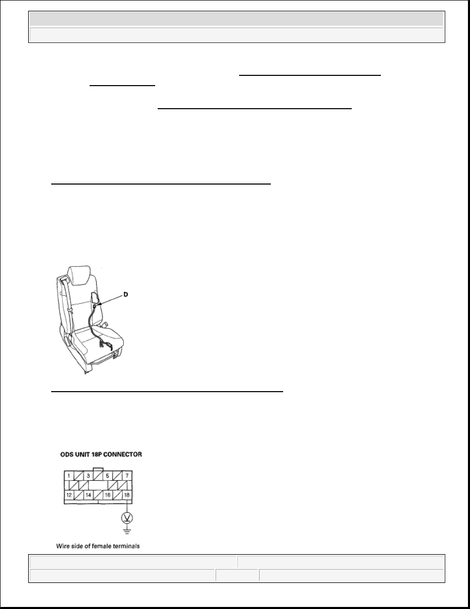
4. Disconnect ODS unit harness connector D (18P) from the ODS unit. 

Fig. 203: Identifying ODS Unit Harness Connector D (18P) 

5. Turn the ignition switch ON (II).  

6. Measure the voltage between the No. 18 terminal of the ODS unit 18P connector and body ground. There 

should be battery voltage. 

Troubleshooting Information (see GENERAL TROUBLESHOOTING 
INFORMATION ).


2007 Honda Element EX 

2007-08 RESTRAINTS SRS (Supplemental Restraint System) - Element


Fig. 204: Measuring Voltage Between ODS Unit 18P Connector Terminal 18 And Body Ground

Is there battery voltage?  

YES -Faulty ODS unit or gauge control module; replace the ODS unit (see ODS UNIT 
REPLACEMENT
 ). If the problem is still present, replace the gauge control module (see REWRITING 
THE ODO DATA AND TRANSFERRING MAINTENANCE MINDER ON A NEW GAUGE 
CONTROL MODULE
 ). 

NO -Go to step 7. 

7. Turn the ignition switch OFF.  

8. Remove the gauge control module (see REWRITING THE ODO DATA AND TRANSFERRING 

MAINTENANCE MINDER ON A NEW GAUGE CONTROL MODULE ). Disconnect the gauge 
control module connector (A) (36P) from the gauge control module. 

Fig. 205: Identifying Gauge Control Module Connector 

9. Measure the resistance between the No. 18 terminal of the ODS unit 18P connector and body ground. 

There should be an open circuit or at least 1 Mohms. 

Fig. 206: Measuring Resistance Between ODS Unit 18P Connector Terminal 18 And Body Ground 

Is the resistance as specified?  


2007 Honda Element EX 

2007-08 RESTRAINTS SRS (Supplemental Restraint System) - Element


YES -Go to step 10. 

NO -Short to ground in the ODS unit harness, floor wire harness, or dashboard wire harness A; replace 
the faulty harness. 

10. Measure the resistance between the No. 18 terminal of the ODS unit 18P connector and the No. 31 

terminal of the gauge control module connector (36P).There should be 0-1.0 ohms. 

Fig. 207: Measuring Resistance Between ODS Unit Terminal 18 And Gauge Control Module 
Terminal 31
 

Is the resistance as specified?  

YES -Replace the gauge control module (see REWRITING THE ODO DATA AND 
TRANSFERRING MAINTENANCE MINDER ON A NEW GAUGE CONTROL MODULE
 ). 

NO -Open in the ODS unit harness, floor wire harness, or dashboard wire harness A; replace the faulty 
harness. 

DTC 91-1X ("X" CAN BE 0 THRU 9 OR A THRU F): SHORT TO GROUND IN THE SRS 
INDICATOR CIRCUIT 

1. Clear the DTC memory (see CLEAR THE DTC MEMORY WITH THE HDS ).  

2. Turn the ignition switch ON (II), and check that the SRS indicator comes on for about 6 seconds and then 

goes off. 

Does the SRS indicator stay on, and is DTC 91-1x indicated?

NOTE:

Before doing this troubleshooting procedure, review SRS Precautions and 
Procedures (see PRECAUTIONS AND PROCEDURES ) and General 
Troubleshooting Information (see GENERAL TROUBLESHOOTING 
INFORMATION ).


2007 Honda Element EX 

2007-08 RESTRAINTS SRS (Supplemental Restraint System) - Element


YES -Go to step 3. 

NO -Intermittent failure, system is OK at this time. Go to Troubleshooting Intermittent Failures (see 
TROUBLESHOOTING INTERMITTENT FAILURES ). If another DTC is indicated, troubleshoot 
the DTC. 

3. Turn the ignition switch OFF. Disconnect the negative cable from the battery, and wait for 3 minutes.  

4. Disconnect SRS unit connector A (28P) from the SRS unit (see step 9 on ).  

5. Remove the gauge control module (see REWRITING THE ODO DATA AND TRANSFERRING 

MAINTENANCE MINDER ON A NEW GAUGE CONTROL MODULE ). Disconnect the gauge 
control module (36P) connector (A). 

Fig. 208: Identifying Gauge Control Module (36P) Connector 

6. Measure the resistance between the No. 11 terminal of SRS unit connector A (28P) and body ground. 

There should be an open circuit or at least 1Mohms. 

Fig. 209: Measuring Resistance Between SRS Unit Connector A (28P) Terminal 11 And Body 
Ground
 

Is the resistance as specified?  

YES -Go to step 7. 


2007 Honda Element EX 

2007-08 RESTRAINTS SRS (Supplemental Restraint System) - Element


Content   ..  133  134  135  136   ..