Honda Element. Manual - part 124
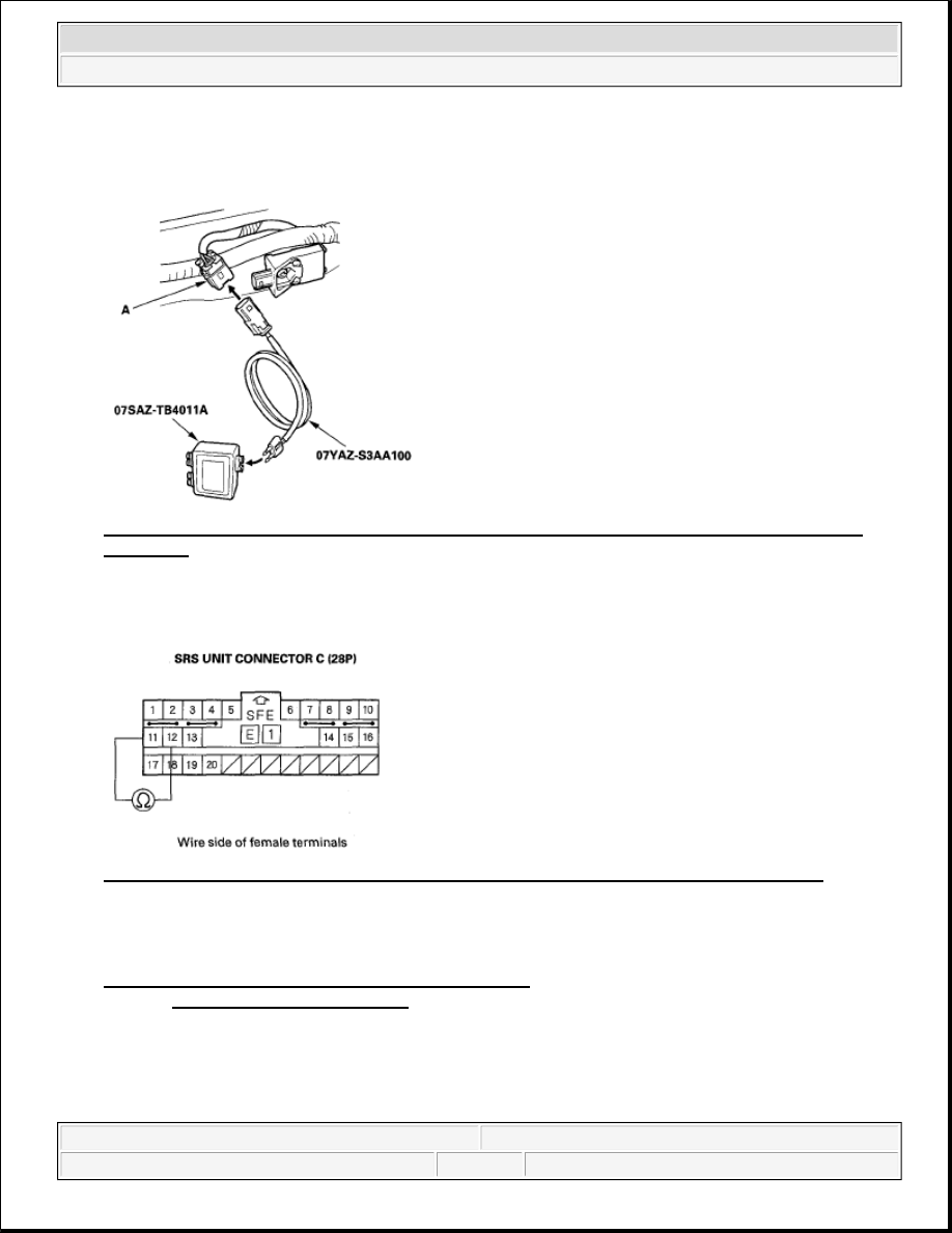
13. Connect the SRS inflator simulator (jumper connector) and simulator lead H to the floor wire harness 2P
connector (A).
Fig. 150: Connecting SRS Inflator Simulator And Simulator Lead H To Floor Wire Harness 2P
Connector
14. Measure the resistance between the No. 11 and No. 12 terminals of SRS unit connector C (28P). There
should be 1.0 ohms or less.
Fig. 151: Measuring Resistance Between SRS Unit Connector C (28P) Terminal 11 And 12
Is the resistance as specified?
YES -Faulty left side impact sensor (first) or SRS unit; replace the left side impact sensor (first) (see
SIDE IMPACT SENSOR (FIRST) REPLACEMENT ). If the problem is still present, replace the SRS
unit (see SRS UNIT REPLACEMENT ).
NO -Open in the floor wire harness; replace the floor wire harness.
DTC 44-1X ("X" CAN BE 0 THRU 9 OR A THRU F): NO SIGNAL FROM THE RIGHT SIDE
IMPACT SENSOR (FIRST)
2007 Honda Element EX
2007-08 RESTRAINTS SRS (Supplemental Restraint System) - Element